Continue to Site

Eng-Tips is the largest engineering community on the Internet

Intelligent Work Forums for Engineering Professionals

  • Congratulations GregLocock on being selected by the Eng-Tips community for having the most helpful posts in the forums last week. Way to Go!

Miami Pedestrian Bridge, Part XII 34

Status
Not open for further replies.

zeusfaber

Military
May 26, 2003
2,466
A continuation of our discussion of this failure. Best to read the other threads first to avoid rehashing things already discussed.

Part I
thread815-436595: Miami Pedestrian Bridge, Part I

Part II
thread815-436699: Miami Pedestrian Bridge, Part II

Part III
thread815-436802: Miami Pedestrian Bridge, Part III

Part IV
thread815-436924: Miami Pedestrian Bridge, Part IV

Part V
thread815-437029: Miami Pedestrian Bridge, Part V

Part VI
thread815-438451: Miami Pedestrian Bridge, Part VI

Part VII
thread815-438966: Miami Pedestrian Bridge, Part VII

Part VIII
thread815-440072: Miami Pedestrian Bridge, Part VIII

Part IX
thread815-451175: Miami Pedestrian Bridge, Part IX

Part X
thread815-454618: Miami Pedestrian Bridge, Part X

Part XI
thread815-454998: Miami Pedestrian Bridge, Part XI

Check out Eng-Tips Forum's Policies here:
FAQ731-376: Eng-Tips.com Forum Policies
 
Replies continue below

Recommended for you

RAB678 said:
To the structural engineers listening> What is the upper bound on the length of this type of span? And the width?

That question is very difficult to answer. There is not enough experience with concrete truss bridges to estimate a practical limit.

The limit would be more than 175'. The concept was not the issue. The main problem was the design details and a failure to identify or address those issues. These were some fairly basic mistakes.
 
It's like looking at the infamous Tacoma Narrows bridge and concluding that the problem was the span.

Ja. translations by Thai people.

In one intonation (there are two others):
"In my experience, when you hear a new Thai acquaintance of the opposite sex begin to replace the more formal KHRAP/KHA with JA (h)/ JA (f) in their speech, it's a sign they feel more at ease in your company and that a friendship (or more) may be developing.
Men don't tend to use JA with each other, unless they are gay.
Can also sometimes be used by older men and women to younger girls/boys (under 12)."
 
Site conditions may govern, or at least weigh heavily (no pun intended) on this issue.
First, I see the forming and casting of a concrete truss with integral deck and roof as being far more intricate than the standard highway sections used everywhere, therefore it will be time consuming and expensive. But these boutique "signature" sites may justify an attempt.
The falsework for a cast in place truss structure would be much like that required for the standard bridge construction so there is little savings there.
And there is a maximum size and weight for ABC construction, as well as site suitability required.
It would have been difficult to set this 174 foot structure if it were necessary to reach, lift, and move from one end.
For those sites which require a long span, I think the cable stay system or the segment cast structures should be more efficient.
Adding 24 feet and making this structure 200 feet long would not have created demands any less known or less knowable than those in the 174 foot span. Reducing this span to 150 feet would not have made the design or importance of any member or connection less critical.


Re: Vance Wiley (Structural)9 Aug 19 02:09

Reducing the span to 150 feet with all other dimensions held makes a huge difference, span would be much lighter. A 200 foot span would have to be much taller. It's interesting to me the sub span of the bridge while having a much shorter span is of the same proportions as the main span. So therefore, the sub span was over-engineered.

I believe this structure was scaled within reason, but its parameters were in critical region and it was not given attention has such.

Would designing 11/12 in mindset of corbel have helped?
 
I think it could have helped. There was discussion of this in the past two weeks or so. I see the primary influence as being the development of the "capture" of horizontal thrust from 11 and returning it some distance in the deck, maybe 40 feet, allowing the complete transfer of that thrust to the PT strands in the deck.
Had the horizontal component of the compression in 11 been properly connected, in this case as a strut and tie design, only the vertical component would remain. It was that vertical component that FIGG addressed in the Power Point show on March 15. Apparently they were assuming the horizontal thrust was adequately developed.
Even with a strut-tie design, the flat construction joint at the deck surface would be a problem and should have been handled differently - with a square construction joint, thereby avoiding the sliding present in the joint as constructed.
 
JRS said:
Reducing the span to 150 feet with all other dimensions held makes a huge difference

150/175*100%=85%. Reducing the shear to 85% is not going to help that much. It would still be over-stressed. When designing a bridge, you need to be more than 15% or 20% from failing and that doesn't even including the live load or other load combinations. Designing the connections properly could have been done at 175' or 200'. That is the fundamental issue.
 
Re: Earth314159 (Structural)9 Aug 19 05:01

Thank you for correction. I was for some reason thinking factor was sixteen based on deflection.
 
jrs_87 said:
...Would designing 11/12 in mindset of corbel have helped?..

I certainly think so. If they'd cast the deck monolithically with a raised corbel the full width of the decorative pylon above 12, there'd have been more room for rebar to reinforce the shear connection between 11 and the deck, and especially with that part of the deck that contains the longitudinal PT tendons. The construction joint could have been normal to the compression force in 11, or at least have "captured" (Figg's words) 11 in the corner between a vertical face of the corbel and the deck.
 
Greetings to all:

I have been out of this forum for a while so I have not read most many of the post. Therefore, bear with me.

Now that the OSHA report has been published this is some of my additions:

1. The whole thing started with the absence of a note in the Contract drawings saying hat the deck concrete must be roughened to 1/4" before casting the truss struts. This changes the factor in the formula of the capacity of the connection #11strut/deck from 1.0 to O.6. This is why the pics in the OSHA report show the strut sliding on top of the deck. The calcs from FIGG indicate the assuption of the 1/4"roughening.
. Furthermore, the costruction practice and the FDOT spects does not provide that type of roughness unless it is specified in the Contract Drawings. MCM probably just cleaned the deck without chipping or adding a bonding agent (my guess)

2. The 8 #7 column bars in strut #11 can not be used in evaluating the Shear-friction capacity of the connection because they are in compression. AASHTO does not clarify that in the LRFD Code. But if you look at the shear-Friction section of the ACI code it really clarifies that. I am not sure if the OSHA report or the calculations of the members of this forum has accounted for this.

3. So the displacements (craks) pics indicte that the connection bars where mostly working as dowels and not in the shear-friction mode. #11 strut was being contained longitudinally by #12 column.


4. And now, my big guess is that when they attempted to restress the PT bars, the additional axial/bending loads rotated the strut end, additionally compressed the small fillet connection #11 to #12, broke the rebars, pushed into the side of ##12 and flew away: "it happenned"

5. Hwoever, for me it does not matter the specific set of events in the last miliseconds before the failure. It was clear from the cracks that the bridge was in serious trouble and that nothing should be under it. The death of all six people could have been avoided. So far nobody has accepted their responsability in public (as far as I know). And FIGG apparently still says publicly that it not their fault (as far as I read it in the publications out there). If anybody knows otherwise, please tell me.

6. The deaths could have been avoided by closing the road and having a bunch of engineers (including FDOT Central Office) evaluating the situation before touching the structure.

Live long and prosper.

 
"Ja" sorry, a translation. Posted in error for you. I thought meant jovial apologies. In America not same.
You say it short for donkey rear? In my country similar lingo is hard to work with. Condolences. Perhaps bridge too far.
 
The Mad Spaniard (Structural)9 Aug 19 21:04, good post. My response to item 2:

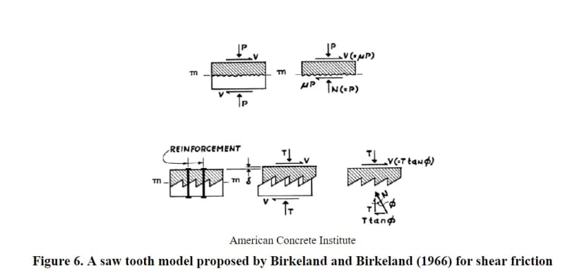
sawtooth_okdzhp.jpg


Saw tooth model 1/4" amplitude roughening

PDF > Link

Birkeland and Birkeland
 
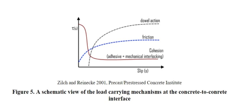
Dowel action offers near zero resistance at start of slip motion.

coh_k22dle.jpg
 
jrs_87 (Mechanical)10 Aug 19 09:57 [URL unfurl="true" said:
https://search.proquest.com/openview/a489f3425d869...[/URL]]
Great link. Wish I could read all of it.
Comments on the general subject of shear friction:
I think FIGG was correct to discard cohesion as contributing. It seems to me all cohesion would be lost due to the slip necessary to mobilize cross-plane reinforcing in tension.
The 1/4" of intentionally roughened surface is commonly achieved by raking the surface before the concrete has set, using something like a heavy asphalt rake. The surface is rough - you would not want to slide into second base on it. But then comes the next pour - with maybe 1/2 inch and 3/4 inch aggregates. The aggregates cannot fit into the 1/4" rake marks, so only the paste and sand can "mate" to the roughened surface. And then there is the slump required, the vibrating of concrete to completely fill all voids, and the fact that the closest access for a tradesman is 16 feet above the joint. What could go wrong?
I have seen rock pockets at the bottom of pours - honeycombing - with little paste to lock the aggregates at the surface of a previous pour.
So with no aggregates in the toothed interlock, when does the concrete matrix simply powder and then lubricate the moving joint? Of course it has already failed if it moves that much.
Regarding the 800 psi upper bound - is that applied to the sum of all components - cohesion AND friction from clamping of reinforcing AND normal force across the joint?
 
The Mad Spaniard said:
MCM probably just cleaned the deck without chipping or adding a bonding agent (my guess)

The 8 #7 column bars in strut #11 can not be used in evaluating the Shear-friction capacity of the connection because they are in compression.

The roughness can be done (In my experience, this is usually done) before curing. It is actually easier for the contractor to leave a deliberately roughened surface. It is really hard to say what a 0.25" or 6mm of roughness really is but it is difficult to have any other reasonable descriptor.

I don't know about the US codes but I know in other codes, the bars in "compression" can be used for the shear friction capacity. This is done for pour joints in shear walls. Even though the element is in compression, the bar itself is still in tension. The compression in the concrete increases as slip is induced at the joint (the compression in the concrete increases by the amount the steel is in tension). The bar is in tension even though the member is in compression. This implies that the compression stress should be limited in regions of high shear friction stress since the steel is no longer helping resist the compression stresses. The maximum shear stress is limited by a function related to the compression strength but it is not limited by the actual compression stress at the joint. It may make some sense to limit the shear in the joint by both the compression strength and stress but that is not how our code is written (maybe different in the US). The same applies to the compression zone of bending elements.
 
Vance Wiley said:
I think FIGG was correct to discard cohesion as contributing. It seems to me all cohesion would be lost due to the slip necessary to mobilize cross-plane reinforcing in tension.

I am skeptical of using the cohesion component and prefer to ignore it. Unfortunately, the way the code is written is that a single lower phi factor applies to both the steel and cohesion components (I am assuming the US code equation is written the same way). The code writers need to multiple out the brackets in the resistance equation and use one phi factor for the steel and another factor for the cohesion. That way we don't have to under-count the steel component if the cohesion is ignored (set to zero). I can't figure out why the shear friction equation was written in this fashion. Any ideas?
 
Isn’t the steel supposed to be perpendicular for shear friction to be valid?

How does it work in this case?
 
Vance & Epoxybot, re peer reviews,

It seems that designers or contractors appointing independent reviewers is the norm now or at least widely accepted. Technical independence rather than commercial. I believe there are several reasons including the owner not wanting to administer another contract, not wanting to face delay claims ("YOUR review is late"), and not wanting variation claims ("YOUR reviewer requires a higher standard than your tender documents did"). All the problems are on the contractor's side of the fence.

Public authorities often have consultant panels (pre-approved consultants) from which the reviewer will have to be drawn. Not sure about FDOT.

Having another office of the design firm do the review isn't necessarily shady. In-house reviews are all that most designs get. It can work well because the discussions can be more frank and honest as they happen behind closed doors.

Some reports say the Berger review was by a single engineer. It would have been better with a number-cruncher working under the guidance of a guru.
 
Status
Not open for further replies.

Part and Inventory Search

Sponsor