Continue to Site

Eng-Tips is the largest engineering community on the Internet

Intelligent Work Forums for Engineering Professionals

  • Congratulations GregLocock on being selected by the Eng-Tips community for having the most helpful posts in the forums last week. Way to Go!

Miami Pedestrian Bridge, Part XII 34

Status
Not open for further replies.

zeusfaber

Military
May 26, 2003
2,466
A continuation of our discussion of this failure. Best to read the other threads first to avoid rehashing things already discussed.

Part I
thread815-436595: Miami Pedestrian Bridge, Part I

Part II
thread815-436699: Miami Pedestrian Bridge, Part II

Part III
thread815-436802: Miami Pedestrian Bridge, Part III

Part IV
thread815-436924: Miami Pedestrian Bridge, Part IV

Part V
thread815-437029: Miami Pedestrian Bridge, Part V

Part VI
thread815-438451: Miami Pedestrian Bridge, Part VI

Part VII
thread815-438966: Miami Pedestrian Bridge, Part VII

Part VIII
thread815-440072: Miami Pedestrian Bridge, Part VIII

Part IX
thread815-451175: Miami Pedestrian Bridge, Part IX

Part X
thread815-454618: Miami Pedestrian Bridge, Part X

Part XI
thread815-454998: Miami Pedestrian Bridge, Part XI

Check out Eng-Tips Forum's Policies here:
FAQ731-376: Eng-Tips.com Forum Policies
 
Replies continue below

Recommended for you

3DDave said:
If you suggest increasing the length of the deck to produce an overhang beyond 12

Yes I am saying if the diaphragm extended further past #11 the punchout wouldn't have occurred so easily. Much bigger failure surface and the failure block has to intersect the PT cables. Maybe there are other reasons not to make the diaphragm thicker, but a thicker end block would have increased the capacity.


And yes steel reinforcement to anchor it back is very important.
 
Tomfh said:
That's why I mentioned to widen/thicken the diaphragm, to provide greater length for the strut and tie forces. Same as when you widen out a pier cap beyond the piles to provide additional engagement between the struts and the bottom ties, to prevent the struts blowing out the sides before they get a chance to grab onto the ties.

As you say, the struts and fan are pushing out toward the north edge of the diaphragm but that is okay when doing a strut and tie model. As long as there is at least one viable load path and enough surrounding steel to meet the ductility requirements, there won't be an issue with the diaphragm. I don't know if you do many strut and tie models or not but there are requirements for minimum percentages of steel in each direction to ensure that there can be a redistribution of load path. The method is very flexible for designing disturbed regions like this and is well proven. In this case, the compression struts and anchors are all within the depth of the deck. Thickening the diaphragm is not harmful, it may helps a little bit but it is not necessary. It is more important to flare out the base of #11 and drag the horizontal components to the south side of the flare before it is transferred into the deck. You also want to note on the drawings to roughen the pour joint to an amplitude of 6mm.

There is a bit of coincidence in the failure in that that south side of #12 and the back side of the diaphragm are closely aligned to one another which adds to the confusion as to what the relevant parameters are.
 
3DDave said:
I think the correct answer was to have steel tie the reinforcement in 11 to the reinforcement of the deck rather than depending on cement in the concrete to handle that job.

Just to be clear, we are definitely saying there has to be vertical steel through the joint. Reducing the shear stress allows the congestion of the required steel to be minimized. The percentage of vertical steel for the shear area goes down but the total vertical steel through the joint goes up.

The horizontal component in the flare has to be dragged southward with horizontal steel above the pour joint. This distributes the shear friction/interface more evenly.
 
Earth said:
As you say, the struts and fan are pushing out toward the north edge of the diaphragm but that is okay when doing a strut and tie model.

In this bridge the strut is the #11 and the tie is the deck PT cables.

As constructed the strut load did not get into the ties. It simply detoured around those PT cables, and burst out of the back of the diaphragm.

If the diaphragm thicker (i.e. deck longer)that couldn't have happened.

Flaring out the base of 11 achieves much the same thing as lengthening the diaphragm. Provide a wider fan which can catch more steel.
 
Tomfh said:
In this bridge the strut is the #11 and the tie is the deck PT cables.

As constructed the strut load did not get into the ties. It simply detoured around those PT cables, and burst out of the back of the diaphragm.

If the diaphragm thicker (i.e. deck longer)that couldn't have happened.

Flaring out the base of 11 achieves much the same thing as lengthening the diaphragm. Provide a wider fan which can catch more steel.

The punching occurred on the top surface of the diaphragm/deck. It doesn't mater where the south side of the diaphragm was located (it could have been set further south). It wouldn't have increased the punching capacity since the south side of the punch started at the south side of #12 where the vertical #11 bars were located. Thickening #12 and placing the vertical #11 bars further south would have increased the punching capacity.
 
Earth said:
It doesn't mater where the south side of the diaphragm was located (it could have been set further south).

I'm not talking widening diaphragm to the south. I mean extending it to the north, so that the failure cone is bigger, and the PT rods extend further past #11 so as to help intercept the blow out cone.
 
Tomfh said:
I'm not talking widening diaphragm to the south. I mean extending it to the north, so that the failure cone is bigger, and the PT rods extend further past #11 so as to help intercept the blow out cone.

That makes more sense. Thanks for clarifying that.I wasn't thinking that because of the physical constraints.
 
SFCharlie said:
Is this what Earth314159 meant by square up 11

I can't remember saying "square up 11". Do you have the post available so I can read it and clarify? Thanks.
 
SFCharlie 10 lined up with a fake stay. 12 is where 12 is. 11 had to go from one to the other. Changing 11 means moving 10 and 12.
 
Earth said:
I can't remember saying "square up 11".

I recently used the term "square up" in reference to the #11 to deck construction joint. I.e. make the joint perpendicular to the member, so as to eliminate the fatal shear friction interface.
 
3DDave said:
SFCharlie 10 lined up with a fake stay. 12 is where 12 is. 11 had to go from one to the other. Changing 11 means moving 10 and 12.

The base of #11 and #12 don't necessarily have to intersect. You could move the base of #11 to the south and cantilever the abutment to the south. This would have helped.
 
Earth said:
I wasn't thinking that because of the physical constraints.

Yes maybe the geometry can't be made to work. I don't know for sure. Maybe its impossible to make a heftier block for 11 to bear against.
 
Tomfh - Earth314159 Sorry I attributed the suggestion to the incorrect author.
As Earth314159 says, 11 doesn't need to abut 12, Couldn't the concrete between 11,12 be wider and higher?

SF Charlie
Eng-Tips.com Forum Policies
 
Flaring out the base of 11 achieves much the same thing as lengthening the diaphragm.
Making the base of 11 much wider would not have restricted foot traffic - they intended to pour column 12 much bigger to support the pylon for the fake pipe stays.
EDIT: Sheet B-56 shopws it to be 5 feet wide. END EDIT.
Making all the connections of diagonals to the deck much longer on both sides (under the diagonal) would not have limited any usable space - a person cannot walk closer than about 5 feet to the joint without hitting the diagonal with one's head.
 
What steel arrangement would be best for tying the punched out concrete beyond #11 back into the deck? Regular longitudinal L-bars and U-bars?
 
Tomfh said:
What steel arrangement would be best for tying the punched out concrete beyond #11 back into the deck? Regular longitudinal L-bars and U-bars?

Right at the punched area I would likely try to use U-bar with anchor bars at the inside corners of the bends.

At the other locations (at flares and haunches) you get the best anchorage with ties. However, if the flares vary in height, I might use a combination of ties and U-bars. You also want an arrangement that helps for deck punching for the interior joints. The joints at the canopy would need some reshaping as well (but not as bad since there is a shear plane between the blister and deck as well as the underside of the canopy). These are the kinds of details that you spend lots of time designing and thinking about. I would discuss different options of the shape of the flares with the client. The reinforcing depends on the shape of the flare. I generally try to look for patterns and consistency in a design.
 
SFCharlie said:
As Earth314159 says, 11 doesn't need to abut 12, Couldn't the concrete between 11,12 be wider and higher?

Yes, absolutely. I was thinking the same thing. Moving the base of #11 to the south helps in multiple ways. You just need to rethink the design of the abutment.
 
Just a thought. Trying to stay close to original design profile. And it probably wouldn't hurt to fan out all connections. Of course to save time and money, you could build it to original specs. But I don't know how well that will work...........

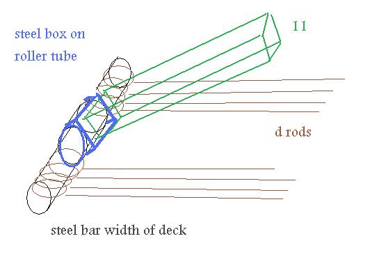
end_capture_nzhe86.jpg

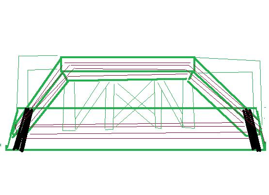
Next pic shows redesign using upper pic with what I call endless cable running thru and around entire middle to capture forces at ends. You would add my concept to original design.
crude_cable_drawing_pe4kmh.jpg

Sorry I ran out of crayons.
While we're at it. Why not relocate the drain pipe. Fill in the hole. And run some bolts completely thru the canopy down thru the verticals and out the bottom of the deck. So maybe like the bottom doesn't fall out. Get to work people. Let's see the new design revisions.

And would somebody please address the canopy drain pipe issue? Certainly someone will never throw a "soda" can up there and clog the system. Just what we need more weight.
 
I find it interesting that the longest span of 174 feet has only 2 feet on the pylon and they saved 4 feet for the shorter span of 96 feet. They could have easily made it 175 feet long with a 3 foot diaphragm and had room to support the shorter cip span.
I would caution that moving the base of 11 southward will move the "joint" of 11 to deck off the pylon and leave moments and shears in deck to deal with.
 
Status
Not open for further replies.

Part and Inventory Search

Sponsor