Continue to Site

Eng-Tips is the largest engineering community on the Internet

Intelligent Work Forums for Engineering Professionals

  • Congratulations KootK on being selected by the Eng-Tips community for having the most helpful posts in the forums last week. Way to Go!

Miami Pedestrian Bridge, Part XII 34

Status
Not open for further replies.

zeusfaber

Military
May 26, 2003
2,466
A continuation of our discussion of this failure. Best to read the other threads first to avoid rehashing things already discussed.

Part I
thread815-436595: Miami Pedestrian Bridge, Part I

Part II
thread815-436699: Miami Pedestrian Bridge, Part II

Part III
thread815-436802: Miami Pedestrian Bridge, Part III

Part IV
thread815-436924: Miami Pedestrian Bridge, Part IV

Part V
thread815-437029: Miami Pedestrian Bridge, Part V

Part VI
thread815-438451: Miami Pedestrian Bridge, Part VI

Part VII
thread815-438966: Miami Pedestrian Bridge, Part VII

Part VIII
thread815-440072: Miami Pedestrian Bridge, Part VIII

Part IX
thread815-451175: Miami Pedestrian Bridge, Part IX

Part X
thread815-454618: Miami Pedestrian Bridge, Part X

Part XI
thread815-454998: Miami Pedestrian Bridge, Part XI

Check out Eng-Tips Forum's Policies here:
FAQ731-376: Eng-Tips.com Forum Policies
 
Replies continue below

Recommended for you

SFCharlie said:
Thank you for your thoughtful answer.
(...guess FIU would have had to issue bump caps...)

You are welcome. I think Apple and Samsung should issue bump caps with each cell phone that they sell. [bigsmile]
 
Tomfh said:
I meant a foot wider, to increase the horizontal thickness.

In my view there was failure of the cold joint for the first 100mm or so, and beyond that it's an overall concrete punching failure thru the diaphragm. If the diagram was 3 foot thick not 2 foot thick it couldn't punch out the way it did.

I see what you mean. Although if you solve the interface shear issue, you don't have an issue with the diaphragm thickness. There was a significant increase of the vertical steel through the joint at #12. That helped transfer the loads into the deck just above the diaphragm. I believe that is why the shear plan dips down above the diaphragm. The diaphragm does punch but with proper detailing, the load would be properly distributed to the deck PT before there would be any punching on the diaphragm. I hope that makes sense. It is a bit difficult to explain.
 
Deck Shortening and diagonals.
174 feet of concrete will shrink about an inch. FDOT required form mods so diaphragms could move. Of course the diagonals will shrink also. The shrinkage of different parts may not track together due to intervals between casting.
Shortening of the deck under PI is about 5/8 inch.
Some diagonals are loaded with PT which must have caused shortening. Some diagonals were not stressed and resisted shortening. The canopy had light PT at erection, with most to be added when the back span was completed.
Pretty much a scramble of conditions.
Would not shortening of the deck have moved the bottom of diagonals closer together and caused moments in the rigid joints? Maybe not enough to be of concern. In a pin connected truss, shortening of the deck would have caused the structure to increase in height.
FIGG was aware of some potential stresses, because they specified a sequence for applying PT loads.
Plenty of questions, few tested answers.
I wonder if perhaps the compression diagonals should have been precompressed with PT to create more compatible strains during curing?
 
Tomfh,

We don't know when the cracks observed in February first occurred or what form they took, but I can guess.

I wasn't suggesting that the canopy and the end vertical were stiff enough to resist the shortening. Nothing is stiff enough to prevent shortening due to shrinkage. But there were also the diagonals, member 11 in particular, operating in concert with the canopy. They all tried resisting, but found it impossible and instead cracked.

Shrinkage would be the dominant factor here, with PT adding a bit. A lot of shrinkage cracking could have occurred prior to application of the prestress.
 
earth said:
Although if you solve the interface shear issue, you don't have an issue with the diaphragm thickness.

Which interface shear are you referring to?

In my opinion you need to:

A- ensure #11 cant slip across the deck (hence the need to square up the joint)

B- ensure the deck can’t punch out due to the load from #11 (hence idea to make diaphragm wider/stronger/more reinforced)


hokie said:
We don't know when the cracks observed in February first occurred or what form they took, but I can guess.]

The OSHA report says the cracking occurred when sharing removed. Your older link also says it cracked when on ground in conditions mimicking the real conditions, ie supported at ends.

Do you have any other evidence the cracking was caused by shrinkage/shortening forces?

But there were also the diagonals, member 11 in particular, operating in concert with the canopy. They all tried resisting, but found it impossible and instead cracked.

Yes, but how would the 11/12/canopy assembly provide sufficient restraint to a shortening to deck to fail the node. As Earth point out, it’s fundamentally a truss. Shortening a member won’t cause a node to rupture.
 
Tomfh said:
Which interface shear are you referring to?

In my opinion you need to:

A- ensure #11 cant slip across the deck (hence the need to square up the joint)

B- ensure the deck can’t punch out due to the load from #11 (hence idea to make diaphragm wider/stronger/more reinforced)

Interface shear is shear friction (I don't know about the US code but it is called interface shear in the code that I use). In this case, I mean the slipping between the underside of #11 and the top of the deck.

The punching can't occur unless you first get an interface shear failure. If you stop the slip, punching would not have occurred. Once you have sufficient shear friction capacity, you have a strut ( a "fan" shaped strut) and tie model that can distribute the load to D1 and the remainder of the load to D2.
 
Hokie66 said:
We don't know when the cracks observed in February first occurred or what form they took, but I can guess.

I wasn't suggesting that the canopy and the end vertical were stiff enough to resist the shortening. Nothing is stiff enough to prevent shortening due to shrinkage. But there were also the diagonals, member 11 in particular, operating in concert with the canopy. They all tried resisting, but found it impossible and instead cracked.

Shrinkage would be the dominant factor here, with PT adding a bit. A lot of shrinkage cracking could have occurred prior to application of the prestress.

We have photos of the first appearance of shear cracks when the shores were first removed. The base of #11 and #2 had the first signs of shear friction cracks.

The canopy would have had to act as a strong back for the deck PT to cause shear cracking at the base of the diagonals. The bending stiffness of the canopy is orders of magnitude less than the stiffness of the truss as a whole. It is possible for deck PT to cause bending in the canopy joints but without a sufficiently stiff strong back, PT causes upward camber and gravity causes sag.

In a structural determinant truss, no matter the shrinkage or PT, the member force is zero without external loads but the truss shape does change.
 
earth said:
Interface shear is shear friction (I don't know about the US code but it is called interface shear in the code that I use). In this case, I mean the slipping between the underside of #11 and the top of the deck.

Yes. I was just clarifying whether you meant the 11 to deck construction joint, or if you were adding up shear planes inside the deck too.


The punching can't occur unless you first get an interface shear failure.

I may be misunderstanding you, but this strikes me as fundamentally wrong. The deck can grab onto the deck with infinite strength and the deck can still tear out in cone/punching failure.
The deck can simply tear out behind member 11, which it almost did (the deck tore out about 100mm into member 11)
 
One difference in our assessment is that most here consider this to be a truss, while I don't. I think it acted as a frame, with bending in the members and joints similar to a Vierendeel truss.
 
I agree without Earths’ assessment that the frame stiffness plus shortening effects are insufficient to break the node, and that the cracking is due to truss loading forces under gravity.
 
Five hundred and two days have passed since collapse. I'm guessing NTSB report will be released within 30 days.

Would someone here care to draw free body diagram with everything south of 9 just a moment and with hinges in deck and canopy at top and bottom of 9? What forces would develop in 11 resisting rotation at hinges?
 
I calculated it earlier at around 940 tons; about halfway down on page 1 of this thread.
 
jrs_87 said:
I'm guessing NTSB report will be released within 30 days.
NTSB has suggested the the report will be available "in the fall". A "docket" should become available 30 days before the hearing. I just checked and the docket is apparently not available yet.
In the mean time, I recomend the previous (apearantly November 2018) two updates:
Update and Update2

SF Charlie
Eng-Tips.com Forum Policies
 
hokie66 said:
One difference in our assessment is that most here consider this to be a truss, while I don't. I think it acted as a frame, with bending in the members and joints similar to a Vierendeel truss.

Even with a vierendeel, the canopy and verticals would both have to be relatively stiff to cause the shear issue when the PT in the deck is tightened. In this case, the canopy does not appear to be stiff enough to cause an issue. It is quite flexible compared to the truss as a whole.
 
Tomfh said:
I may be misunderstanding you, but this strikes me as fundamentally wrong. The deck can grab onto the deck with infinite strength and the deck can still tear out in cone/punching failure.
The deck can simply tear out behind member 11, which it almost did (the deck tore out about 100mm into member 11)

It actually can't tear out if you have a enough capacity in the strut and tie model from the pour joint shear plane to the deck PT anchors. The horizontal shear at the base of #11 has to be dragged back to get a more even distribution of stress at the shear plane (and you want a flare at the base of #11 as previously mentioned). However, there is enough capacity in the compression strut/fan to carry the load to the D1/D2 PT anchors. There is also enough transverse steel and PT to resist the horizontal tension parallel to the diaphragm.

The punching that occurred took place within the depth of the deck. The diaphragm thickness did not play a significant role in the punching capacity. The distance from the size #11 south vertical bar in #12 to the north face of the deck was a more critical factor in the punching capacity. There was significant shear friction capacity at the base of #12 member and doweling action from the size #11 bars (the #11 bars were not well anchored so you only get doweling from the #11 bars but the other bars were better anchored) that allowed the punching to occur. Without these bars, the failure would have been a pure shear friction failure.

With such a short distance between the size#11 bars in 12 and the north face, you could not get a strut and tie model to work and hence the punching shear failure occurred.
 
Earth said:
It actually can't tear out if you have a enough capacity in the strut and tie model from the pour joint shear plane to the deck PT anchors.

That's why I mentioned to widen/thicken the diaphragm, to provide greater length for the strut and tie forces. Same as when you widen out a pier cap beyond the piles to provide additional engagement between the struts and the bottom ties, to prevent the struts blowing out the sides before they get a chance to grab onto the ties.


earth said:
The punching that occurred took place within the depth of the deck. The diaphragm thickness did not play a significant role in the punching capacity.

If the diaphragm thickness was greater the edge distance to the applied load thrust would be greater, a larger cone would have to fan out, which would also intersect the PT cables. The diaphragm was so short that the failure cone skirted around the PT.

There was significant shear friction capacity at the base of #12 member and doweling action from the size #11 bars (the #11 bars were not well anchored so you only get doweling from the #11 bars but the other bars were better anchored) that allowed the punching to occur.

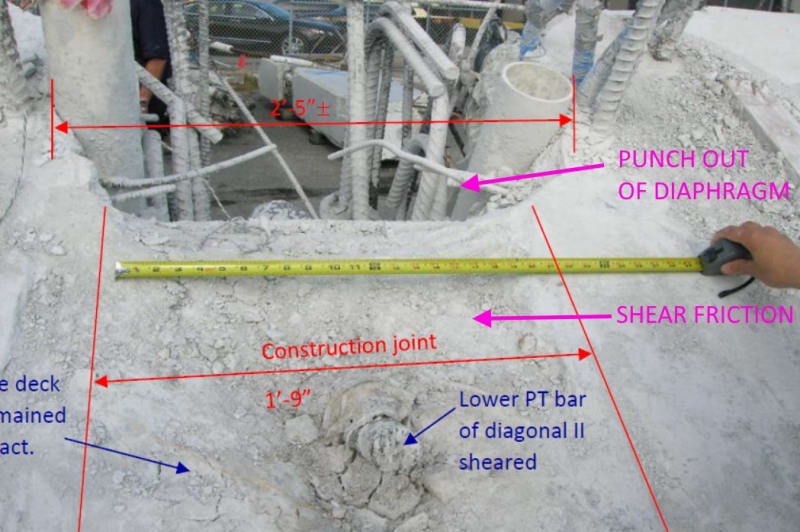
Yes, it was a combined failure. Horizontal shear friction for some distance, and then a cone failure surface fanned out thru the diaphragm. Akin to combined failure often seen in smaller anchors. PINK comments are mine.

SHEAR_FRICTION_vianlk.jpg


So my suggestion was to square out the connection, to eliminate the shear friction aspect. Make the strut dig into the deck directly. And to make the diaphragm stronger/thicker to prevent any punch out failure once the load is in the deck.


In any case I think we agree that one way or another that strut #11 needed to be more strongly anchored!
 
The diaphragm is under the deck of the bridge. Making it wider places more of it under 11, where it does no good, rather than extending past 12. Changing the diaphragm governing dimension along the length of the deck while leaving it flush with the end of the deck doesn't increase its capacity. If you suggest increasing the length of the deck to produce an overhang beyond 12 then that doesn't work well with the pylon or other span.

I think the correct answer was to have steel tie the reinforcement in 11 to the reinforcement of the deck rather than depending on cement in the concrete to handle that job.
 
Status
Not open for further replies.

Part and Inventory Search

Sponsor