Continue to Site

Eng-Tips is the largest engineering community on the Internet

Intelligent Work Forums for Engineering Professionals

  • Congratulations KootK on being selected by the Eng-Tips community for having the most helpful posts in the forums last week. Way to Go!

Miami Pedestrian Bridge, Part XII 34

Status
Not open for further replies.

zeusfaber

Military
May 26, 2003
2,466
A continuation of our discussion of this failure. Best to read the other threads first to avoid rehashing things already discussed.

Part I
thread815-436595: Miami Pedestrian Bridge, Part I

Part II
thread815-436699: Miami Pedestrian Bridge, Part II

Part III
thread815-436802: Miami Pedestrian Bridge, Part III

Part IV
thread815-436924: Miami Pedestrian Bridge, Part IV

Part V
thread815-437029: Miami Pedestrian Bridge, Part V

Part VI
thread815-438451: Miami Pedestrian Bridge, Part VI

Part VII
thread815-438966: Miami Pedestrian Bridge, Part VII

Part VIII
thread815-440072: Miami Pedestrian Bridge, Part VIII

Part IX
thread815-451175: Miami Pedestrian Bridge, Part IX

Part X
thread815-454618: Miami Pedestrian Bridge, Part X

Part XI
thread815-454998: Miami Pedestrian Bridge, Part XI

Check out Eng-Tips Forum's Policies here:
FAQ731-376: Eng-Tips.com Forum Policies
 
Replies continue below

Recommended for you

I guess my reading comprehension and interpretation skills need a little work.

I thought you said
Here is the problem.................
When I said the deck hangs from the canopy.....it does.

That wasn't you? Must have been that silver tongued devil on your shoulder.

Both are ABOUT 25 feet No - you just asked about 2, saying it is longer than 11 so why didn't it fail. So the canopy over 2 has to be longer too. Simple geometry.

when we could cheat and hold it up more inwards....30 feet or so. On either end. Read posts re:FDOT

para 3 not a column in the road ja. Perhaps you would decode this term "ja"?

I just said some of your comments were acceptable. Oh - it's YOUR bridge badge that arrived early?

Do your homework before coming to class.


Vance - RAB678 Please stop sniping at each other. That's not what we're here for. Yes, some diagonals (10,3,8,5, I believe) hang from the top chord of a truss. Even a computer nerd knows that. Let's just get on with what happened to the bridge.
Added (and don't 9,4,7,6, rest on the deck and support the canopy?)
 
Apologies yes indeed are in order.
Sorry, bridge and its discussions sometimes can be aggravating.
Please accept my apology.

I shall place myself in timeout. Listen but do not speak.

"ja" is a term from Thailand. It roughly translates to....fight but fight with good reason.
 
Let's just get on with what happened to the bridge.

Ya, it fell down. Cause was a design issue where 11/12 met the deck. Most everything about the details of exactly what happened is speculation.
 
LionelHutz said:
Ya, it fell down. Cause was a design issue where 11/12 met the deck. Most everything about the details of exactly what happened is speculation.

I think there is a lot more to learn from this collapse. There were certainly multiple design flaws that should have never have happened. However there are many more ethical and procedural questions and changes that need to be made to the profession.

I would like to know the fee structure and how hours were allocated. Other collapses have been linked to too few hours being spent by senior engineers checking the work. I can't help but suspect that a junior engineer took the results from the computer analysis to design the members but then totally forgot to check the transfer of the loads at the joints. The connection design is the hard part that takes many hours. The senior engineers would then assume the joints were designed correctly. I don't know how this bridge passed the independent review process. Again, what were the hours allocated for this procedure? Doing an independent review of the connection design would have taken many more hours than a review of the member sizing. Was that why the connections were ignored? I can only assumed it was ignored since I don't see how else this could have been missed.

There are also ethical components to this disaster and all those issues have to be reviewed as well.

We don't yet have enough information to fully explore the ethical and procedural issues.

I would also suggest that we use a limit states stress design approach rather than a limit states force design method. This is my own opinion but understanding stress more easily and quickly identifies problem areas. It also gives the designer a far greater feel for the behaviour of structures.

Mentoring of young engineers is also lacking and I also suspect this is due to fee structures. We also need to encourage more people into the profession so that engineers do not have to do so much overtime. More engineers means that there will be more hours for reviewing the work that does get done (of course fees also have to go up to do all this).
 
May I post a dissertation of truss action and design? It is about a page and a half, and contains no sniping. It does not address directly the collapse and details of that, but may clarify some concepts about trusses.
If it is considered off course, I will not post it.
 
Vance Wiley (Structural) 28 Jul 19 18:54 said:
May I post a dissertation of truss action and design? It is about a page and a half...
Just upload it as a PDF file and no one should have any issues with it. Even if it's hand-written, you can scan it with a "save-to-pdf" option.
 
OK - here goes.

The FIU Pedestrian Bridge is basically a concrete truss. It has the added complexity of being cast monolithically, albeit there were three basic phases to that casting. The deck was cast, then the diagonals, then the canopy. But the construction joints were intended to create a monolithic state. The diagonals were cast in one phase, and could likely be considered monolithic without conditions, provided they were cast quickly enough to prevent cold joints.

The “added complexity” of being monolithic creates the possibility of bending moments being induced in members by rotation of the joints. So while this structure is not a pure truss, I suspect the designers used a truss analysis to determine the axial forces in the members, and then checked or analyzed the effects of joint rigidity on the diagonal members. And I would concur with that procedure. FEA analysis may make the distinction a moot point and have included everything in one analysis. I think it would be appropriate to not reduce axial forces in members due to continuity, and the simple truss analysis should be used to determine primary forces in the members.

If it can be considered as a truss, here is a definition for that from Wikipedia:

“A truss is an assembly of beams or other elements that creates a rigid structure.[1] In engineering, a truss is a structure that "consists of two-force members only, where the members are organized so that the assemblage as a whole behaves as a single object".[2] A "two-force member" is a structural component where force is applied to only two points. Although this rigorous definition allows the members to have any shape connected in any stable configuration, trusses typically comprise five or more triangular units constructed with straight members whose ends are connected at joints referred to as nodes.
In this typical context, external forces and reactions to those forces are considered to act only at the nodes and result in forces in the members that are either tensile or compressive. For straight members, moments (torques) are explicitly excluded because, and only because, all the joints in a truss are treated as revolutes, as is necessary for the links to be two-force members.”
(Emphasis mine).

One dictate of “truss” design is to provide concentric loads at a joint. This eliminates eccentricity and minimizes (to zero if a true pin) bending and shears in the members. This is accomplished in the layout and dimensioning by passing the neutral axis (or line of action, or centroid) of all members thru the center of the joint. A primary benefit of this concept in a truss of the configuration at FIU is that the vertical components of web members are directly passed from tension in one member to compression in the adjacent member, without passing through another member. The PT rods and anchor plates pass thru to above the canopy and transfer their loads to the blister and canopy as a means of anchorage, and could cause rotation forces which must be supported by the canopy and blister. The downward vertical component of the PT force is considered to be resisted by the compression component of the other diagonal, applied at the center of the joint. The behavior of the joints with lapping PT rods anchored beyond the extremity of the compression member causes me a bit of concern. The compression forces under the PT anchor plates are intersected by the compression in the other member at different angles (depending on the joint). I am unsure about how well this creates an ideal truss joint.

From observing the detailing of this structure, the principal axis or line of action of the web diagonals in this structure seem to comply with this concept. One condition which may not comply with concentricity is the connection of the fake pipe “stays” which align with a diagonal but deliver a vertical load quite eccentric to some joints, but these loads were not in place at the time of the collapse. Vertical loads induced by the weight of the pipes would have been distributed to the joint thru moments in the blister and canopy.

In a horizontal parallel chord truss with joint concentricity, all vertical components of loads are resisted by the diagonals, Loads from above (canopy weight, pipe stays, live load) are considered applied directly over the joint. Tension in a diagonal passes thru the “work point” of the joint, with its vertical component added to the roof load from above and becomes the vertical component of compression in the adjacent diagonal at that joint. The horizontal components are transferred to the top chord (canopy in this case) as compression (increasing the axial force in the canopy or decreasing that force, depending on geometry and force vectors). With a horizontal top chord having only compression, there is no vertical component of that force in the chord which can provide vertical support to the truss. The top chord must carry its weight and tributary loads and deliver those loads to the joint while resisting the flange force in this structure.

With that said, technically, in the case of a simple truss, no diagonals “hang” from the top chord (canopy). They receive their vertical support from the joint. In this case, the canopy is above the diagonals, and while they may appear to “hang”, I do not think the designers intended that to be the case. The vertical component of member 11 would likely have blown thru the 12” thick canopy far more easily than it blew out thru the deck and diaphragm but it did not because member 10 restrained the joint 10/11, intercepting the vertical component of member 11 below the canopy.

It is not impossible to connect a diagonal of either tension or compression some distance from the center of the joint (the lines of action might intersect above the canopy, in such a case). Doing so would apply loads of several hundred kips in this case (lets think compression) to some point away from the line of action of the vertical component of the tension member, and induce serious shears and moments in the roof canopy. That can be dealt with in the design but would require special design and detailing of the canopy in that area. Thankfully the joints appear concentric in this structure.

Every piece of this structure is necessary for the success of this structure. If one element fails, it collapses. In that sense, the success of this structure “hangs” on the proper performance of every component. The canopy is one of the elements which must not fail.

As Ben Franklin said, “We must all hang together, ....“.

Comments expected.
Thank you.
 
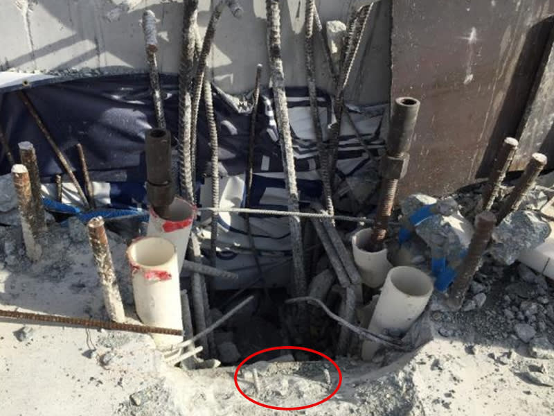
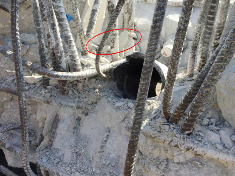
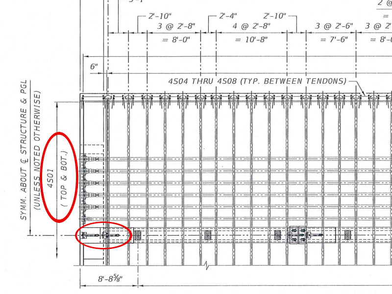
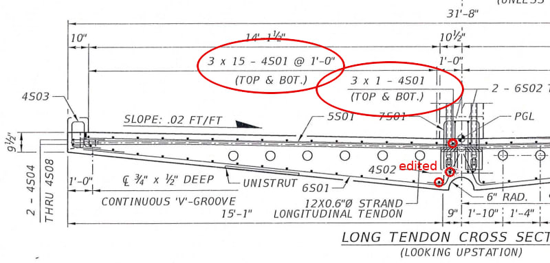
Does anyone have any thoughts or ideas as to why this rebar was stubbed short of column 12 (presumably column 1 as well)? Does the rest of slab rebar stop short of the diaphragm as well? What does 3 x 15 refer to in the end view dwg.? I'm not a structural type so I'm just asking.

edit: end view markup edited to be consistent with rebar indicated on OSHA figures.

OSHA_Figure_xgro4z.jpg

OSHA_2_rlteg0.jpg

Top_View_mo53hy.jpg

Top_View_2_jl4mxd.jpg

End_View.edited_srfp32.jpg

Rebar_Chart_gkxkkl.jpg
 
No idea of why the short rebar but maybe I can help on the 3 X 15 bars.
The bars are available in 60 foot lengths. The "3 x " indicates 3 sets required to make the deck length of 174 feet. Top & bottom left & right is 4 locations of 15 bars each, making 60 bars X 3 sets to make the length = 180 bars. The single bar top and bottom each side at center = 4 bars X 3 sets is another 12 bars required. 180 plus 12 = 192 bars as noted in the table. Extra lengths are used in laps. I have not decoded the "B", "C" dimensions - they usually are leg lengths of bent bars so there is probably a code somewhere designating which legs are noted.
I do not see a note or a reason for holding any of this reinforcing short of the end - 3" clear of the formed end, of course.
 
I think there is a lot more to learn from this collapse. There were certainly multiple design flaws that should have never have happened. However there are many more ethical and procedural questions and changes that need to be made to the profession.


Sure, but not much of that is learned by the speculating here.
 
FDOT STANDARD BAR BENDING DETAILS.
Non standard bends are shown on FIGG drawings.
The FDOT details show leg designations, etc.

EDIT ADD:
Bars 4501 were intended to be TYPE 2 =straight with laps of 1'-9" and total length of 175'- 1". That is 1'- 1" longer than the deck.
That means with maybe starting layout at 8" from south end (larger diaphragm) the bars could extend 1'-9" at the north end for a lap to the back span.
The bars 4501 near the center of the deck may have been held back to reduce congestion in the base area if member 12.
 
This discussion has been going on for a long time, and much of it is about the detailing of the "truss" to take the imposed forces. But this failure was due to neither the analysis or implementation, but rather due to conceptual design. The initial cracking occurred while the it was still on the ground. The deck shortened due to shrinkage and applied compression, and that shortening was resisted by the inclined webs. Cracking resulted. When gravity loading then opened those cracks, it collapsed. The concept was doomed.
 
Thanks Vance, I was looking for that. Regarding "held back", is this the type of detail that would generate correspondence for clarification or would the installer just wing it? Or for that matter are there inspection notices?

Hokie66, the deck shortening would be assisted by PT cable compression and would also promote sagging out of the gate. This still fits with my failure model. Other than that, difficult concepts are the essence of advancement.
 
It certainly became " A Bridge Too Far".
Do you think there is some inherent reason it could not work, or that it is a concept fraught with many conditions requiring attention "outside the box" of normal concrete construction?
The "K braced frame" was basically outlawed, at least in some jurisdictions, because it was a concept to be avoided due to the consequences of failure and the ease with which it could be misused, as I understand. Perhaps a post tensioned concrete truss should be banned for those reasons.
 
Vance,

Without a rigorous program of testing the concept, I think this type concrete truss/frame will never be used again. And I doubt that will happen, as there is simply no call for it. Structural steel works, so why change? There was an opportunity here to load test the frame while still on the ground. That didn't happen, and disaster occurred.

Sym P. le, "advancement" is in the eye of the beholder.
 
LinonelHuntz said:
Sure, but not much of that is learned by the speculating here.

Some of what is discussed is speculation or educated guesses but a lot more of the information has been confirmed in reports, released photos, calculations etc.

For example, we didn't know for certain if the #11 rod was being tightened or loosened until the first NTSB report came out. We didn't know how bad the cracks were until the photos were released. This brings up ethical questions as well technical issues. As more information is released, we learn more.

In my mind, the ethical and procedural issues are more important than the technical issues. As far technical issues go, a well understood failure mechanism at the connection was missed (and other significant design issues).
 
Status
Not open for further replies.

Part and Inventory Search

Sponsor