Eng-Tips is the largest engineering community on the Internet

Intelligent Work Forums for Engineering Professionals

  • Congratulations waross on being selected by the Tek-Tips community for having the most helpful posts in the forums last week. Way to Go!

Miami Pedestrian Bridge, Part XII 34

Status
Not open for further replies.

zeusfaber

Military
May 26, 2003
2,466
0
0
GB
A continuation of our discussion of this failure. Best to read the other threads first to avoid rehashing things already discussed.

Part I
thread815-436595: Miami Pedestrian Bridge, Part I

Part II
thread815-436699: Miami Pedestrian Bridge, Part II

Part III
thread815-436802: Miami Pedestrian Bridge, Part III

Part IV
thread815-436924: Miami Pedestrian Bridge, Part IV

Part V
thread815-437029: Miami Pedestrian Bridge, Part V

Part VI
thread815-438451: Miami Pedestrian Bridge, Part VI

Part VII
thread815-438966: Miami Pedestrian Bridge, Part VII

Part VIII
thread815-440072: Miami Pedestrian Bridge, Part VIII

Part IX
thread815-451175: Miami Pedestrian Bridge, Part IX

Part X
thread815-454618: Miami Pedestrian Bridge, Part X

Part XI
thread815-454998: Miami Pedestrian Bridge, Part XI

Check out Eng-Tips Forum's Policies here:
FAQ731-376: Eng-Tips.com Forum Policies
 
Replies continue below

Recommended for you

MikeW7 said:
I assumed the canopy-11-12 triangle remained intact for a bit, at least until the end of 11 slid past the end of the north deck.

I guess this is where I disagree. I don't see 11 sliding past the end of the deck. It just pancakes or disintegrates while the canopy and 12 struggle with the extra load until 12 is yanked downward by the canopy. I see that in both the dashcam video and the traffic cam video.
 
Sym P. le (Mechanical) 22 Jul 19 06:53 said:
I don't see 11 sliding past the end of the deck.
I seem to remember that the canopy-11-12 triangle was one of the initial theories about the likely failure of the 11-12-deck joint. I reworded the captions so the second picture describes this theory as an IF scenario.
 
MikeW7 said:
... was one of the initial theories ...

It's quite possible there was an event at the 11/12/deck node at the onset of the collapse but as I stated earlier, everything has to move together so I can't see a wholesale departure. That would just relieve the stress on 11 and 12 and leave them in tact.

I see the 11/12 team breaking out of the deck/diaphragm pocket in steps, giving a loud crack each time, starting when the false work was removed. This in turn allows the deck to sag, members to deflect as stress/strain builds up, various tell cracks to show etc.. What if another event caused the lower PT rod to kink or something like that?
 
I've always said that when you watch this collapse in real time it all occurs frighteningly fast and trying to work out which piece failed exactly when is not going to be of importance.

It is very clear that the 11/12 connection to the deck was suffering huge cracking and impending failure before they assaulted it with the tendon tightening exercise. The real issue in that node could easily be the presence of those two PE tubes which moved from an early design further away from no 12 to the final design where they are right next to the 12 member plus a load of smaller tubes appear as well. saikee199 in part V of this thread provides more details and the OSHA report photos have more also. If those PE tubes were cast in a packet then even more shear resistance disappears.

So maybe as has been posited in the last few parts - the 11/12 joint failed by degree during the rod tightening, a bit here then a bit more. All the time the stress on the other nodes, especially 9/10, continued to climb. Maybe 9/10 or 10/11 did fail first leading to blow out of 11/12, but it was wholly due to the failing of that 11/12 joint. otherwise why would the deck or the canopy just decide to fail? The evidence has been pointing at 11/12 being the root cause since about 2 weeks after the collapse and everything just keeps coming back to it.


Remember - More details = better answers
Also: If you get a response it's polite to respond to it.
 
I find interpreting frames of the dashcam video difficult due to the changing angle between the cam and the north end of the bridge. Given that, I tried to measure the apparent end of 12 to the north of the pier in frame 80. The distance from the apparent end of 12 to the bottom of the north end of the canopy appears to be 16% bigger than the original length of 12. Are we seeing a chunk of 12, 11, and/or deck fall off the pier? It seems to be gone in the next frame.

SF Charlie
Eng-Tips.com Forum Policies
 
SFCharlie (Computer) 22 Jul 19 19:43 said:
Are we seeing a chunk of 12, 11, and/or deck fall off the pier?

In the chopper photo posted by Tomfh (Structural) 9 Jul 19 22:19 there appears to be a considerable amount of rubble immediately north of the pier, but no large chunks. Can't really identify the large object hidden in the manlift shadow (between the canal wall and the red beam). Anybody know if there are other shots of that area?

In my N View crop 26423 posted 9 Jul 19 21:45 (just above Tom's post) there isn't a splash ring, bubbles, or cement colored swirls in the canal, so if the image was taken within 15-30 seconds of the collapse it doesn't appear a large chunk went in the canal. Even if it did, by comparing 26422 and 26423 you can see that any evidence on the water surface would have been disrupted as it was swept east (left) by the mini-tsunami caused by the excavator.
 
Great work.
It helps me just to know not everyone uses CAD or PowerPoint today.
The cut ups capture very well the collapse. Your second image, with member 11 still shown, may predict what happened to the bottom of 11 - it is trapped on the corner of the deck for that brief period and was already split when it becomes loaded from its lower side. Half the canopy from 10/11 to the end plus 12 weigh about 35 kips. Add the pull down at 10/11 and that could significantly damage member 11, perhaps causing it to shatter in its lower section.
I did a spreadsheet of dimensions from the bearing at 1 to 10/11(canopy) , then from 10/11 to top of 12, and one of deck dimensions with segments 1 to 9/10 and from 9/10 to the end at the pylon. It calculates the total length as each point (10/11 and 9/10) drop in increments of one foot. It could supplement your cutouts.

FIU_Dimensions_hlasn1.jpg
 
Vance Wiley (Structural) 22 Jul 19 20:46 said:
It helps me just to know not everyone uses CAD or PowerPoint today.
:
I did a spreadsheet of dimensions

I started re-learning a CAD program I was once very familiar with, and also working out a table of dimensions, but gave up because other things in my life have a higher priority. CAD (cardboard-assisted design) seems to be very popular with the YouTube kids nowadays (see Project Binky and Acorns to Arabella for example) so it was kind of an obvious choice for me.

I remember when I was younger I used to work with all sorts of puzzles and building projects (even bound into magazines) that relied on printed cardboard, scissors, tape, and "insert tab A into slot B." Does that sort of stuff exist anymore, or has everything gone "virtual" with no more "hands on"?
 
Spartan5 (Civil/Environmental) 23 Jul 19 13:10

Cool! Free toys AND a slick marketing ploy to sell Canon printer ink by the gallon.

What I seem to remember are puzzles printed on thick paper, bound into a magazine. I also remember buying the whole series of The Incredible Machines games back in the DOS days.
 
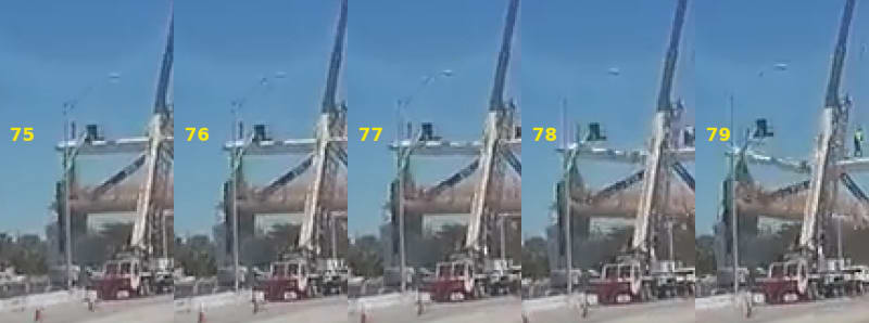
When did 12 depart its perch on the deck?
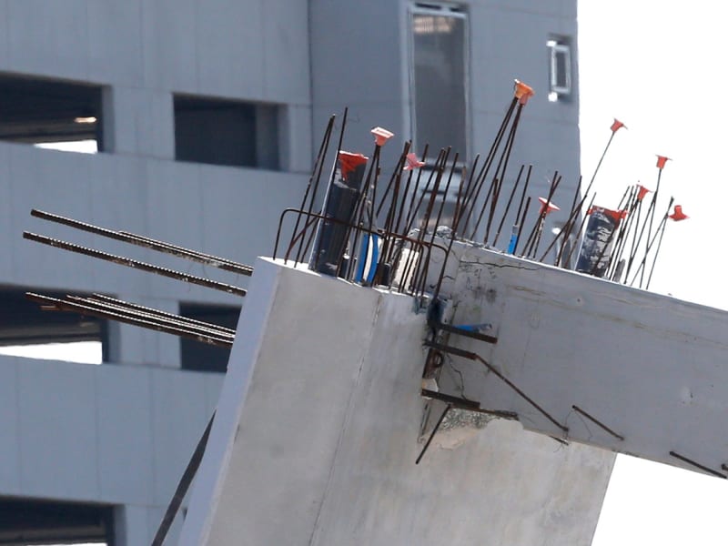
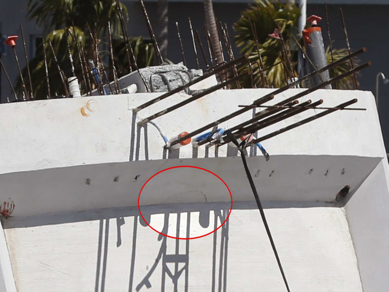
I would like to see comments by all as to amount of damage visible to the north section of the canopy at member 12 and damage to the remaining upper section of member 12. Perhaps good zoomed images - I cannot find severe cracking of the canopy or member 12 at the joint with the canopy.
The canopy is a pretty stiff element. I am guessing maybe 1.5 to 2.5 times a flat section. If anyone has AutoCad and can draw it I think AC can return the section properties - I, S, A, CG, etc. Did a bit of math on a 16 foot segment of a 24.5 ft radius 12” thick, ignoring the oblique orientation of the 1' X 1' segments I think the NA is about 24.153 ft above the Layout Pt, or 0.153 above the bottom of the canopy at the center. Rough “I” is 30616 in^4. Add something for the oblique issue and use maybe 32000 in^4.
The column is easy. 21X34^3/12=68782 in^4. We can use those values later.

Some discussion now. If everything remains connected successfully, members 11 and 12 and the canopy form a stable and well braced system, and 11 protects the joint of 12 to the canopy. But what if 11 loses its grip at either end? Or fails somewhere along its length?
Lets explore conditions when 10/11 drops 3 feet and take member 11 out of the picture. How much stress or deformation can the canopy at 12 and 12 at the top withstand?
When node 10/11 drops 3 feet there are three possibilities with regard to joint canopy/12.
1. No damage visible - the joint remained basically at 90 degrees, and its base departed the top of the deck and moved 2 feet north. 16'/24' X 3' = 2 feet.
2. Complete failure of joint canopy/12, - bottom of 12 could have remained in position on deck. I do not see this as the result when looking at joint canopy/12.
3. Something in between - then some damage would be visible. How much?

FIU_Canopy_12_Bent.jpg1_xiowyx.jpg


To find the possible load conditions at the joint of 12 to the canopy, the canopy is isolated at 10/11 and member 12 is pinned at the base at the top of the deck. The pin simplifies the analysis and allows rotation but prevents lateral movement to the north, simulating a condition in which 12 remained connected to the deck. The canopy is isolated at 10/11 and allowed to move vertically without moving to the south. This is not an acual condition but it allows the approximation of moment capacities and stresses in the relatively undamaged joint of the column 12 to the canopy.
So lets load this 2 member bent with 100 kips at the free end at 10/11. The deflection is about: Delta=PL^2(L+C)/(3EI). L+C is about 24+5 (5 being the equivalent length of canopy section to be same stiffness as the 16 foot column ).
Defl=100K*24^2*29*1728/(3*6x10^6*32000) = 5.01 inches. Pretty stiff.
The moment in the deck and column top is 100K*24'=2400 ft-kips.
Canopy stress is 2400*12*(10.156)/32000=8.14 ksi. That is about failure, but we have not included reinforcing.
Column stress is 2400 'K*12*34”/2/68782=7.11 ksi. The column could survive this moment.
But that is at a deflection of only 5 inches.
If joint 10/11 dropped 3 feet, the stresses on the canopy and column would be much greater. Like 35”/5”=7 times greater. Or in the order of 56 ksi in the canopy and 49 ksi in the column. That is failure levels, and did not happen. We can tell that by observing the canopy and column area of the collapsed structure.
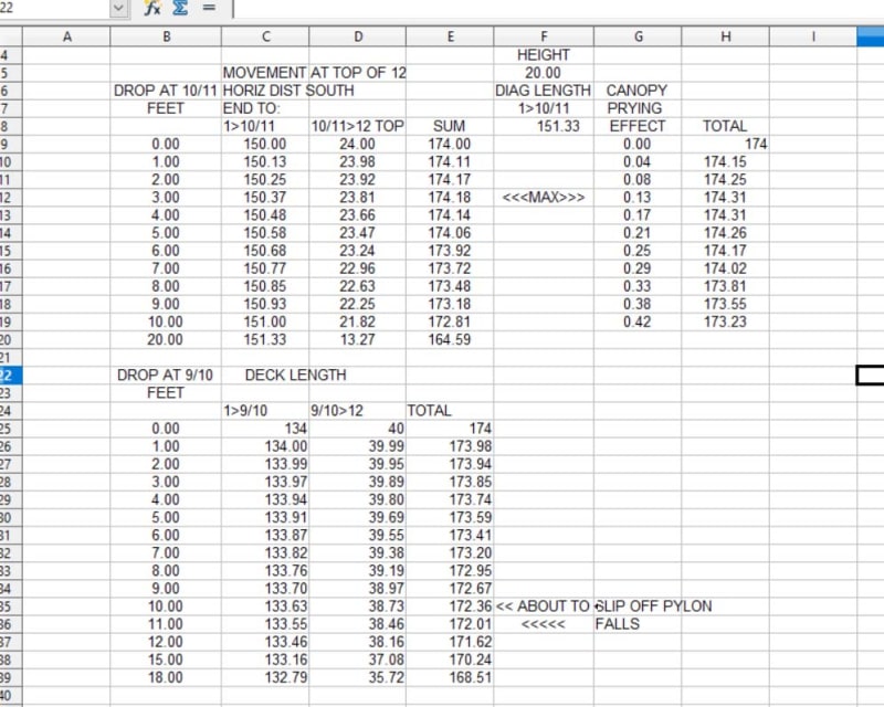
So the column could not have been on top of the deck when joint 10/11 dropped 3 feet. From the dimension results, reading 3 feet drop in joint 9/10, the deck has moved south only 0.15 feet or about 2 inches.
These results are linear, assuming everything remains elastic. So even at the point when 10/11 dropped one foot, the results are 2.4 times the 5” result and stresses, making failure of the canopy/12 joint a certainty - if 12 remained atop the deck.

I suggest 11 and 12 departed the deck as the initial event of this collapse. It must have decoupled from the deck before joint 10/11 dropped a foot or so.
Note - I hope I got the numbers right - I welcome peer review.
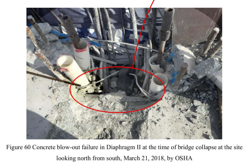
EDIT ADD: One more possibility - if member 11 failed by bursting or because of the splits captured in the photos, thereby allowing joint 10/11 to drop 5", the above calc shows the canopy and member 12 could have delivered about 150 kips northbound to the 11/12/deck joint. That additional 150 kips may have triggered or hastened the blow out and collapse. And the retensioning of the PT rods in 11 may have further damaged 11 to the point of failure.
 
I've tried to view this collapse incrementally, i.e. three foot increments are too large, even when you back it up to one foot, it is too large. Nonetheless, you moved in the right direction. I was thinking more along the lines of fractions of inches to envision the implications of any one element having some freedom to move. This is how I came to the awakening that 11/12 already had separation from the slab and was merely leaning against the rebar that was running the width of the diaphragm through 12, among other.

Your numbers however support my earlier theory that as the span sagged, the load on 11 could grow until it was overwhelmed. Also, as 11 pushes 12 northward, it is necessary that 9/10/deck sags and so doing pulls the deck toward the centre of the span, opposite to the movement of 11/12 and also dropping out from beneath 11, tearing it longitudinally. So, in short, 12 didn't have to leave its perch completely, it just had to shift a little bit more w.r.t. the slab.

The damage to 12/canopy is best seen in these two images. It's hard to tell whether the damage is from the initial collapse or from the collision with the ground. In the sequence, you can see the vertical rebar leaning south but six of the nine rebar are only associated with the canopy, i.e., if the joint is crimped, the rebar won't align with the column. From my previous gif's, I tend to think that the joint initially crimped.

file-20180321-165554-1en0ick.3_ztilko.jpg

Canopy_roof_cracks.2_ubsco5.jpg


Frame 76 gives the first indication of the canopy sagging and the vertical rebar is already leaning south. It's hard to tell if 11 starts to pancake because the truck hasn't stopped yet. There is no significant lateral or vertical movement of 12.

By Frame 77, 11 is already pancaking and in Frame 78, 12 drops and moves independently of 11/slab. Thus, my position is that 12 left its perch in 78, though there was a likely event at the 11/12/deck/diaphragm connection at Frame 75. As I indicated earlier, careful inspection of 75 indicates a puff arising from the joint that was not visible in the earlier frame. That really could be the precipitating event.

75-79_huvgkt.jpg

bridgecollapse.2_fofqgw.gif


The "event" could be the rebar finally letting go. But again, I don't see any giant step movements starting the collapse. It seems likely to me that an impulse from a sudden jarring shattered the node and 11 while 12 was yanked down by the canopy. I don't know how else one could conjure up so much clean rebar.

Rebar_dwg.2_xhlp8k.jpg

Broken_Rebar.2_r3qx22.jpg
 
epoxybot (Structural) 24 Jul 19 20:53 - Now I understand why the "falling man" had his safety harness clipped to the crane hook....

Have a gander at the "safety line" these guys were using:
[ul]
[li]A nylon sling cinched around rebar through its own end loop[/li]
[li]A light-weight pulley clipped to the other sling loop[/li]
[li]13mm climbing rope pulled tight through the pulley and tied off with what appears to be a simple slip-knot. (This was at the north end, so I assume the tightening occured there.)[/li]
[/ul]

Crop of expoxybot's image, rotated 90 degrees:
Safety_Tie-off_pzgf51.jpg
 
Sym P. le
Thank you for the clear close-up photos. The first one shows damage I had not seen before. There it appears the concrete of the lower deck surface is failed, indicating rotation between the canopy and column. The second photo shows cracking in the raised diaphragm at the north end of the canopy, suggesting the beginning of a punch thru failure. I can no longer support the concept that the joint is undamaged and it likely failed to hold the original angle between the canopy and column. After viewing the photos, I do not think the canopy/column joint can resist the 2400 ft-kips presented in my post of yesterday.

as the span sagged, the load on 11 could grow until it was overwhelmed

I am not sure this fits, unless 11 fails internally and effectively shortens. Because the support of the north end of this trussed structure depends on member 11 successfully supporting its loads and holding node 10/11 in its original position, there should be no "sag" until 11 had failed to support its loads. If 11 failed to support the loads under static conditions, it seems unlikely that member 11 would support greater loads than those that caused its failure. The same can be said of member 10, but to a lesser extent, and the failure was not in 10.

If the cracking of the deck photographed at the base of 11 and 12 on March 13 represent a movement of one inch northward, the corresponding drop in node 10/11 would be 1.5 inches. The change in geometry would not increase the loads on member 11 significantly (approximately 1%). From the calc presented yesterday, and which assumed the joint canopy/12 remained intact, the 1.5 inch drop would be 1.5"/5" X 100kips =30 kips load on the bent comprising the canopy and 12. That is possibly within the capacity of the joint, and could have introduced 45 kips force to the north at the deck joint. That could have been the added load that triggered the collapse.
I agree that there is much to be revealed at very small distortions. I jumped to 3 feet because that would have moved the bottom of 12 two feet north and basically off the deck, introducing a different condition. That is assuming joint canopy/12 remained as cast, of course.
Thank you for the photos and discussion.

 
I'll post these for consideration. They are images of the failed 12 rotated with a structural dwg. imposed over it. The scale works well as the discoloration of the concrete on the tab at the base of 12 indicates the deck height. The height from T.O.S. to underside of canopy at the column is approx. 15'. The formwork imperfection seen just above the number 12 would be at eight feet above the slab.

Ignoring the mess at the base is not for the feint of heart but these images give an idea for the location of significant diagonal cracks that occurred in 12.

file-20180321-165554-1en0ick.4.overlay_nl34gs.jpg

file-20180321-165554-1en0ick.5.overlay_wouv4j.jpg
 
While looking for images taken immediately after the collapse I noted that only 3 people are responsible for most of them:
[ul]
[li]All chopper pictures were by Pedro Portal[/li]
[li]Ground images were taken by Joe Skipper and Wilfredo Lee[/li]
[/ul]

If you're still looking for good pictures, search for those names, images, and restrict the search dates to 3/15/18 to 3/31/18.

I found this shot by Portal that might be new

ADD: In the Portal image, the two short beams at base of the north pier have been there since at least March 1st - they are visible at the very beginning of the N. View timelapse dated Mar 1-19.
 
Status
Not open for further replies.
Back
Top