Continue to Site

Eng-Tips is the largest engineering community on the Internet

Intelligent Work Forums for Engineering Professionals

  • Congratulations GregLocock on being selected by the Eng-Tips community for having the most helpful posts in the forums last week. Way to Go!

Miami Pedestrian Bridge, Part XII 34

Status
Not open for further replies.

zeusfaber

Military
May 26, 2003
2,466
A continuation of our discussion of this failure. Best to read the other threads first to avoid rehashing things already discussed.

Part I
thread815-436595: Miami Pedestrian Bridge, Part I

Part II
thread815-436699: Miami Pedestrian Bridge, Part II

Part III
thread815-436802: Miami Pedestrian Bridge, Part III

Part IV
thread815-436924: Miami Pedestrian Bridge, Part IV

Part V
thread815-437029: Miami Pedestrian Bridge, Part V

Part VI
thread815-438451: Miami Pedestrian Bridge, Part VI

Part VII
thread815-438966: Miami Pedestrian Bridge, Part VII

Part VIII
thread815-440072: Miami Pedestrian Bridge, Part VIII

Part IX
thread815-451175: Miami Pedestrian Bridge, Part IX

Part X
thread815-454618: Miami Pedestrian Bridge, Part X

Part XI
thread815-454998: Miami Pedestrian Bridge, Part XI

Check out Eng-Tips Forum's Policies here:
FAQ731-376: Eng-Tips.com Forum Policies
 
Replies continue below

Recommended for you

 
Wonderful graphics. Outstanding. I have long thought the use of real images overlaid with drawings created the most informative representations.
Now we can see how the damaged member 12 fits into the picture.
I wonder if NTSB saved the piece you show? I do not recall seeing any pieces in the rubble big enough to reconstruct the part of 11 and 12 just above the deck.
The photo link just posted by MikeW7 to a pic by PORTAL has good detail, but mostly small rubble visible at the pylon.
Thanks for the graphics.
 
Vance, thanks for your response, please excuse me for not taking enough time to consider all of your approach. It certainly made sense and ensured that we consider a broad range of scenarios.

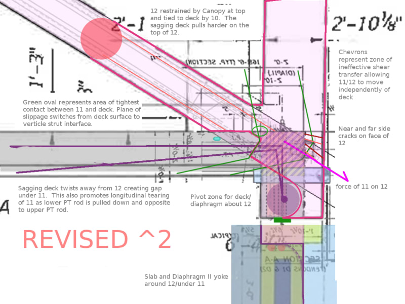
The model that I suggest is a dire predicament for 11. To be sure, 12 is firmly committed to the diaphragm below the drain pipe but this is no relief for the structure as a whole as the deck/upper diaphragm are not picking up the longitudinal forces from 11 as intended. The key to my failure model, is that the distance between 12 and 10 at the deck level is free to increase with no functional restraint and 11 does not need to shorten as the initiating event of the catastrophe (as I initially thought). The more the structure sags, the worse the incident angle becomes for 11 while also enduring induced bending moments, longitudinal tearing at the base, and PT rod tensioning. 11/12 just need to free themselves of the last vestige of restraint in the pocket and its game over.

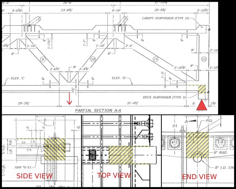
At the risk of being an arrogant fool, I'll repost two images that best explain my model once again. The chevrons indicate surfaces of ineffective load transfer, essentially creating a pocket which allowed 11/12 to move independently of the deck/upper diaphragm. I struggle to concede that this failure can be referred to as shear failure or punch out because the unintended reality does not rise to that level of sophistication. Clearly there was a straw that broke the camels back, but all I can do is speculate. This structure was far more robust than I thought but it wasn't enough.

Deck_11_Overlays.2..12_gkhhmy.jpg

Consider_This_sp3jcp.png
 
[quote Sym P. le][/quote]
My thought is "don't ignore the obvious" - the members 11 and 12 were causing serious cracking in the deck, indicating an imminent failure. So I think that is where it all started - and I think that agrees with you.
From there to the ground it is a progressive collapse with a pretty clear path, and luckily we have real time video and some great enhancements by members here. We do not have a black box, but we have dash cams.
As diagonal 11 lost its ability to support node 10/11 adequately, node 10/11 began to move downward, as you state. With 11 compromised, the load path to the support pylon relied more and more on the canopy from 10/11 north to member 12, and on the deck, from node 9/10 north to the pylon. I suspect the geometry of the truss was basically intact from the south end to nodes 9/10, member 10, and node 10/11 until the bending failure of the canopy and deck (they folded), with some allowance here for the effect of the moment induced by 11 at node 10/11.
The geometry of the 11-12-canopy element requires node 10/11 to drop 2 to 3 feet before the base of 11 and 12 can slip over the end of the deck (assuming 11 is sufficiently intact and can maintain the dimensional relationships. Node 9/10 drops about the same distance as 10/11, and the spreadsheet posted earlier indicates dropping node 9/10 by 3 feet pulls the north end of the deck maybe 2 inches.
IF 11 and 12 remained connected while being pushed over the end of the deck, their weights and that of the canopy and the canopy portion of the truss weight from the shifting load path were supported by the underside on 11 and the corner of the deck (or were sliding thru the "yoke" slot). Another 5 to 7 feet of fall and the deck slips off the pylon, dropping 11 across the corner of the pylon, and destroying the lower part of 11 and 12. Member 11 almost lay on the deck surface as node 10/11 dropped and as the deck tilted down on its way off the pylon. See the "paste-ups in color" previously posted.
That's my story and I'm sticking to it - - - for now.
Of course when 9/10 hit the roadway, more bays of the truss pancaked.
 
Can someone please explain this “yoke” concept? What is the yoke?
 
The "yoke" concept is related to the same principles as involved in the kitchen.
If an egg is cracked and dropped to far the "yoke" splits wide open upon hitting the pan.
Hence the egg is ruined. Similar and applicable, in laymen's terms.
Sorry. Just had to..................
 
As I recall, it was first coined by Sym P. le (Mechanical)28 Jun 19 07:07 and seemed rather descriptive to me. It basically refers to the north end of the deck as seen in the NTSB yard with a slot missing where 11 and 12 once were. I see it as referring to the slot left behind.deck on each side of the slot.
Origins probably relate to ox drawn carts.
 
Mr Vance I have to disagree with your statement. It must be flawless.
Saying that " With 11 compromised, the load path to the support pylon relied more and more on the canopy from 10/11 north to member 12, and on the deck, from node 9/10 north to the pylon."

I think you are stating the canopy at 12 is holding up the bridge.
I beg to differ.
Why? Well because it doesn't.

(Alright, I'll give you this............Probably 90% of the bridge's weight should be held up by 11 and 2.
Some per cent goes to deck on piers and 1 and 12 supporting canopy at ends! only. I am allotting 10% for ends only. Actual numbers....IDK......?
BUT 12 and 1 should be considered as a form of 2 horizontal stabilties. Now getting this right after moving and settling would be an engineers nightmare. This is a part of the problem.)

And if this was the case. Isn't South end...1 to 2 diagonal longer?
Shouldn't it fail first? Meaning if the South canopy is being held up by 1 being the main support.
Its length should produce a quicker failure?
But 2's base is most secure and it's connection is what holds up the canopy.
Consider...why would you want to hold up a 175 foot long 975 ton bridge at the ends.....
when we could cheat and hold it up more inwards....30 feet or so. On either end.
175 now becomes roughly 125 feet.
Would it not be a better bet to support such bridge at 125 feet?
BUT...........your diagonals better not fail.
South end did not fail. 2 was more capable of this. 11 was not.
Obviously other considerations are in order. Ones that we know thru pictures, drawings and the obvious.

11 base was lacking. It failed first. Compare and contrast the two ends. Why not South end first?
Simple, look at the failed side. What was different?

A: 11 undersized, inadequate footing strength (MAIN CONCEPT see note 1:), lack of symmetry (also MAIN CONCEPT), cold joint. Just bad design. Get over it.

Note 1: There is just no way the transfer of forces involved in 11 could EVER be resolved at the deck and 12. 12 should not even be considered as a block.

Picture this... deck longitudinal cables running around a steel bar, 6 inches" ? in diameter, running width of the deck. A steel box possible able to slightly pivot would then capture 11. 11 would be inserted into it.
This would certainly be a more ideal way to capture these longitudinal forces.

Basically you are making a huge door hinge with a box welded to it for 11.

You can't do this as designed. Why not just throw the egg in the air and see how your yoke responds.

Over and over same same same outcome.....splat..........see A:

There's is probably at least 1.5 million pounds of force on 11 base. Play if you want....but.....
This park is closed for renovations.

Reword it. Try again. When I can't see errors in it. And your story is beyond critique, I'll let you know.
Put it out there, one end to the other. Describe it all. I'll pick it apart for you.
If you want, but then again......who am I?
Any questions? just press submit.
 
Btw Sym p le your drawing is good and concepts are good. Why not trust yourself?
Vance is good also.
Personally I find the canopy as the better part of the bridge.
The curves, wings and rigidity of it are interesting.
By far of the models I made... canopy.
Truss connections at deck lacking.
Torsional aspects of deck to truss during dynamic loading questionable.
Cat 5 resistance....futile.
 
How do you think this bridge would have performed under earthquake? Failed node aside, would those web members have been ok resisting the lateral load from the canopy? Seems like a decent lump of concrete sitting atop some sticks.
 
I think you are stating the canopy at 12 is holding up the bridge.
Only for the brief instant before gravity overtook inertia and it began its downward travel. But there were two load paths available after 11 failed. The Canopy on column 12 and the Deck on the pylon were paths for load because they continued to the support. There was no way they had the capacity to support the structure, so that is now 3 failures - first 11, then canopy, then deck. If they had enough capacity tp support the structure after 11 failed, they would have provided redundancy. And I recall your post saying the deck hung from the canopy.

Isn't South end...1 to 2 diagonal longer?Shouldn't it fail first?
I think you know this, but every comic needs a straight man.
The flatter angle provides a greater length to transfer shear to deck. Member 2 is much larger. The south Diaphragm is over 3 feet thick, while the north diaphragm is 2 feet.

Would it not be a better bet to support such bridge at 125 feet?
Sure - right in the center of the second lane of traffic. Nice bridge. Did you study at Texas Tech? On another forum they have a professor touting a dead German named -Muller-Breslau- from about 1850 who discovered putting a column in the center of a span helped. So he espoused that as a cure. I was cut off after I asked if one column helps, it then creates 2 spans, requiring 2 more columns, and so forth until it is a wall and not a bridge.
Note 1: There is just no way the transfer of forces involved in 11 could EVER be resolved at the deck and 12.
It would probably still be in the air if 11, 12, and the north diaphragm were as robust as their counterparts at the south end and if the reinforcing was adequate and the construction joint properly prepared. Formed sockets and strut/tie design have been discussed. Check posts by FortyYearsExperience.

Straight man wants a raise. Close the curtains.
 
Vance said:
It would probably still be in the air if 11

Yes if the diaphragm was 3 feet thick instead of 2 feet thick it probably wouldn't have punched out. Much bigger failure surface, which would also have intersected PT cables.
 
Vance - the irony is that the FIU bridge did have a support in the middle of the span. That's where it failed. I hope those students develop a healthy skepticism for what their instructors tell them.
 
Before I was blocked I reminded them that the Golden Gate bridge did not have a column in its center. I was told the suspension cables provided support for the center. I guess they did not comprehend that the truss was providing center support in this case.


Forces in the longitudinal direction should not be much of a problem. Not so for forces/motions perpendicular to the length. The canopy is a single mass structure atop columns which cantilever from the deck. The deck is not a particularly stiff element in torsion about the longitudinal axis. Serious concerns about the natural frequency of the system.
The deck should be adequate as a flat beam to span the 174 feet.
What I do not understand, even in non-EQ areas, is failing to form a "cradle" at the south end and north end, to prevent any perpendicular movements at those supports. It would have been so simple to do, without defeating the freedom the bearing pads provided.
I would not recommend this structure in Seattle.

This is from 4 years ago - This you gotta watch. From drilling the ocean floor they have learned that it has happened 40 times over the last 10,000 or so years. That is every 240 years on average. It has been about 320 years since the last one. Listen for the size of the tsunami the last time.

 
Tomfh (Structural)26 Jul 19 04:06
"How do you think this bridge would have performed under earthquake?"
Having been through an earthquake in '89, NO WAY. With cold joints at the top and bottom of the web? Earthquakes just keep accelerating back and forth for what seems an eternity, this increases the gaps every cycle. The highest energy in a large quake is at about 1/2 to 1 cycle per second at about 1g. Imagine tipping it on its side. They didn't want it to tip more than 1/2 degree.

SF Charlie
Eng-Tips.com Forum Policies
 
So correct. If the seismic motions fit with the natural frequency of the structure, creating resonance, it is all over. This structure has no dampening available to absorb the energy - except for the concrete being ground up in failure zones.
 
Vance Wiley (Structural) 26 Jul 19 08:35 said:
That is every 240 years on average.

Lots of hyperbole in the video - here's a list of many, many more videos. The RANGE of years figured in the 240 year average is something like 200-900 years, so the futurecast for an earthquake is "more likely" not ASAP. As more and more people are educated about the risks, the PNW has been legislating code upgrades in the area expected to be worst hit by the earthquake, and designating tsunami zones which include evacuation routes and restrictions on certain type of new structures (schools, fire houses, etc.) In many areas none of this will matter because the combination of earthquake damage and soil liquefaction will render all escape routes useless before the tsunami, a miles-wide wedge of displaced water, is pushed onshore and overflows everything left standing.

I grew up in an area that's also "overdue" for a major earthquake that will cause massive destruction and possibly a much larger disruption to the transportation network, the New Madrid Seismic Zone that's centered near Memphis TN. The area surrounding the Mississippi River rests on thousands of feet of sediment deposits, and a major earthquake will liquify this sediment and possibly destroy every structure near the MS River from St. Louis to SE Arkansas, including rail lines and highways. There isn't a lot of education or prep work being done because when a large quake happens, there will be no escape... I remember a discussion of some sort, possibly in high school, that basically said we're letting you know about this so you'll understand what's happening as you die, or why you'll wish you were dead if you somehow survive.

I sometimes wonder how much different this country would look like if early settlers (and especially insurers) were aware of all dangers zones: active seismic faults, Tornado Alley, areas prone to major flooding, forest fires, hurricanes, and so on.


Status
Not open for further replies.

Part and Inventory Search

Sponsor