Continue to Site

Eng-Tips is the largest engineering community on the Internet

Intelligent Work Forums for Engineering Professionals

  • Congratulations KootK on being selected by the Eng-Tips community for having the most helpful posts in the forums last week. Way to Go!

Miami Pedestrian Bridge, Part XII 34

Status
Not open for further replies.

zeusfaber

Military
May 26, 2003
2,466
A continuation of our discussion of this failure. Best to read the other threads first to avoid rehashing things already discussed.

Part I
thread815-436595: Miami Pedestrian Bridge, Part I

Part II
thread815-436699: Miami Pedestrian Bridge, Part II

Part III
thread815-436802: Miami Pedestrian Bridge, Part III

Part IV
thread815-436924: Miami Pedestrian Bridge, Part IV

Part V
thread815-437029: Miami Pedestrian Bridge, Part V

Part VI
thread815-438451: Miami Pedestrian Bridge, Part VI

Part VII
thread815-438966: Miami Pedestrian Bridge, Part VII

Part VIII
thread815-440072: Miami Pedestrian Bridge, Part VIII

Part IX
thread815-451175: Miami Pedestrian Bridge, Part IX

Part X
thread815-454618: Miami Pedestrian Bridge, Part X

Part XI
thread815-454998: Miami Pedestrian Bridge, Part XI

Check out Eng-Tips Forum's Policies here:
FAQ731-376: Eng-Tips.com Forum Policies
 
Replies continue below

Recommended for you

Sym P. Le
The FIU video with SE View (Bridge-PG5-Mar-1-19-2018-1000K-1080.mp4) has a running clock in upper LH corner that advances 1 minute each frame. It only shows members 1-10, however. The collapse occurs at 11:38.

The SW View video (Bridge-PG6-Mar 1-19-2018-1080.mp4) doesn't have a clock, but it is almost the same length, 14:54 versus 14:47, so it was probably shot at 1 fpm as well.

It wouldn't take much effort to use them figure the North View frame rate, but it's bedtime for me so I'll have a look tomorrow.
 
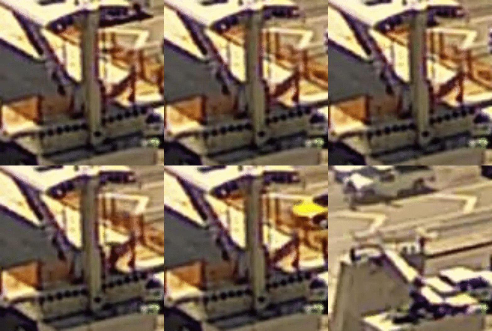
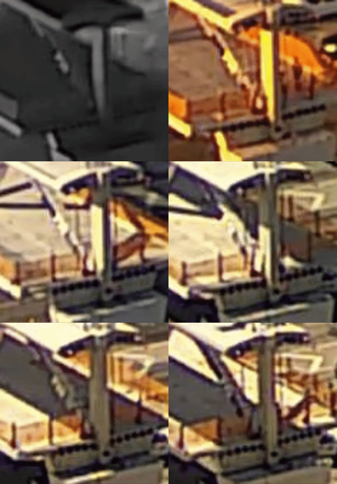
I added a ZIP file of North View closeup images enlarged by Nearest Neighbor interpolation to my post of 16 Jul 19 02:17, [highlight #E9B96E]highlighted with tan background[/highlight]. You should use both the smooth and chunky versions to guide your assessments.

ADD: I also added a second ZIP containing a batch of 100 control images taken at the same time on the previous day so you can see what the North View closeup looked like when it wasn't being worked on.
 
MikeW7, basic question. In your posted GIF, why does the back side of member 12 have a very large jog in it about 6' up from deck?
 
After spending 2 days wrapping my head around all the grotesque torture the bridge endured in its final minutes, I have a few questions:
[ul]
[li]Is it practice at all to photograph or record structures as they are being tensioned/detensioned? That is, take a reference "before" shot followed by a continuous sequence (or recording) of the structure as work is done. As I've found out, it is very easy to see displacements with no special processing, so it should be a simple matter to make "heat maps" of the changes, especially if physical markers are applied before hand, or if a laser pattern is shone continuously on the structure.[/li]
[li]Shouldn't it be mandatory to do this type of recording when unplanned work is done? I know it's an added expense (extra guy, equipment, etc.) but holy crap after watching and re-watching the closeups all weekend I was constantly asking myself why in the hell did they keep going when it was so, so obvious that they were literally tearing the bridge apart.[/li]
[li]In a case like this where traffic is present, should a crew chief like Hanson have the legally protected authority (moral or otherwise) to jump the chain of command and make a phone call directly to a traffic agency like FDOT?[/li]
[/ul]
 
TheGreenLama (Structural) 16 Jul 19 14:2 said:
... why does the back side of member 12 have a very large jog in it ...
This "bulge" is present in the North View timelapse all the way back to when the bridge was installed, but photos around that time don't show any sort of protusion other than the 8" drain pipe that extends out about a foot.

My guess is that the "bulge" is an interpolation artifact related to the drain pipe. If you look at the PB-NN comparison images in my 16 Jul 19 02:17 post, you'll see that the horizontal extent of the drain is not apparent in the black-gray pixels, so the interpolation routine saw those pixels as a flat oval shape and probably just conformed some of the tan background pixels to surround it. This bulge is formed by a small area of about 5x10 raw pixels, so it should be easy to understand that when each of those pixels is replaced by a block of 16x16 interpolated pixels you're sometimes going to see the appearance of wierdly shaped "details" that don't really exist.

High power enlargements can be enhanced to "guesstimate" the shapes hidden in a small group of pixels, but not the details, and sometimes the "guesstimations" are incorrect. That's why I've been stressing that you should only look at original pixels when you're making critical judgements, because that's the only real data that exists. If you can't see it in the pixels, it ain't real....

 
MikeW7 Great work, Thank you!
I seem to see the east edge of the top of the deck slightly tip down away from the diaphragm in the last frame or two before the collapse? I moved the right half of my browser window off screen, so the motion there would not distract or influence me. Can that be real?

SF Charlie
Eng-Tips.com Forum Policies
 
SFCharlie (Computer) 16 Jul 19 16:07 said:
I seem to see the east edge of the top of the deck slightly tip down away from the diaphragm ... Can that be real?

If you read my 16 Jul 19 15:38 reply to TheGreenLama you'll see that the raw pixels representing the extended drain pipe were recorded in such a way that its North-South extension appears as a flat, right-left horizontal oval. I just looked at the canopy area by simply moving the crop window up, and did not observe any kind of vertical movement. Using an analogy similar to the drain pipe mystery, I think the apparent vertical movement we are "obviously" seeing is in fact an interpolation artifact of what is actually the northward kickout of the 11-12-deck joint and diaphragm area that OSHA described as a blowout.

We are all in uncharted waters here. We have to understand that what we are seeing is very "real" in some way, but the actual reality behind it is subject to interpretation, so we need to develop a set of interpretation standards before this devolves into a quagmire of competing SWAGs.


ADD: ZIP file of last 44 frames of North View closeup, cropped to include the entire north end (canopy, member 11, deck, and pier top). This time I remembered to put them in a folder. I also added this ZIP file link to my original post.

ADD: I'm editing my original post with ADDs as new insights are discovered, such as this "Is it vertical or flat?" conundrum.

ADD: GIF of canopy frames 26412-26423

North_View_canopy_frames_26412-26423_ho2ydv.gif
 
In my experience , limited to slabs, beams and building components, record photographs have not been taken. Measurements were taken to compare elongation with ram force as standard procedure, and measurements of relaxation and elongation were required by my drawings when PT strands were to be relaxed and restored for some purpose.
But, like just about everyone in the US, I have no experience with posttensioned concrete trusses. To my knowledge, no one has seen a PT concrete truss succeed, but many have now seen the one example fail. In this case, I have seen no evidence of an attempt to monitor crack progressions with more than a felt tip pen and a tape measure. It is common practice to monitor and quantify cracking using transparent overlapping plastic grids and recording movements to quite small increments. That is from 20 years ago, and valid today, but no doubt supplemented by electronic strain recording today.
Without verification on my part, I would estimate that the majority of PT work at construction sites is in slabs of buildings and girders of highway structures. The problems encountered in this work are pretty well worked out by now. I see no indication of problems with the PT in the canopy or deck in this structure, probably because, at least in part, it is so similar to the countless thousands of miles of PT installed in similar conditions. The web members are a bit more unusual in their application of PT. Relatively short members, dramatic changes in force directions at joints (nodes), members under PT forces carrying tension working with common reinforced members in compression, joints with rigidity, PT anchor plates with high bearing pressures in joints loaded by normal reinforced compression from a different direction - and the list goes on. Trusses work - the devil is in the details.
Having had VSL as the PT contractor on a project, I can say the personnel encountered were efficient, worked carefully, and understood well their work. As a piece at a time, there is nothing unusual in the PT of this structure. As a complete assembly, it is far more complicated. I am not sure that those complications are a problem that the PT contractor is supposed to solve.
But I have strayed from the focus.
A question - is there some "sharpen" filter that can now be applied to your enlarged images? Without creating new information that did not exist ?
 
MikeW7 You have done so much work, I can't complain. The new crops do not show as much of the east edge of the deck as the old ones. This is where I though I saw the slight rotation downward about the east-west axis.
ADD Oh, I guess that I was looking at the shadow of the top of the orange safety barrier, not the edge of the deck. My bad!
 
Vance Wiley (Structural) 16 Jul 19 18:02 said:
is there some "sharpen" filter that can now be applied to your enlarged images? Without creating new information that did not exist ?

Viewing these interpolated images is the equivalent of trying to figure out what's behind a wall of glass bricks. There is only so much you can do to make it look more normal.

You have to remember that the PB (smooth looking) enlargements are representing the exact same detail information that's present in the NN (chunky looking) enlargements, and no amount of filtering is going to recover the details that were lost when the original scene was digitized into chunky pixels. It's frustrating because the smooth edges look more realistic than the chunky blocks, but it's an illusion...
 
SFCharlie (Computer) 16 Jul 19 18:15 said:
I guess that I was looking at the shadow of the top of the orange safety barrier

Yeah, it's the shadow of the safety netting, which appears as a fat line because the sun is at high noon. I had problems with it as well until I realized that the shadow was just starting to creep onto the west edge of the deck when the bridge collapsed.

Another spooky coincidence, like the flash of reflected sunlight off the manlift arm just as the north end blew out.

CSI work is fun!

ADD: The fact that the North View images were shot in burst of 3 followed by a delay can be confusing as heck also. You're watching something change slowly over 3 frames then BAM. This is especially true with shadow movements.


MikeW7, I hate to throw cold water on your lengthy and very detailed post, but what I think we're seeing in the GIF is not real. Member 12 moves up and down WITHOUT any associated noticeable horizontal movement. I don't see how this is possible. Particularly the upward movement--and seen from a camera that's how far away?
 
TheGreenLama (Structural) 16 Jul 19 20:30 said:
Member 12 moves up and down WITHOUT any associated noticeable horizontal movement. I don't see how this is possible.
:
... and seen from a camera that's how far away?
SFCharlie (Computer) 16 Jul 19 21:10 said:
...does the canopy go up and down with 12?

If it were some kind of artifact, why is it visible only in this region, and why would similar but smaller disturbances be visible in the same region, and only during the time period that the canopy crew was working?

The camera distance is not a factor because the entire image is uniformly focused and rock steady. There's no heat shimmer, focus drift, etc. There are a couple of frames with camera shake in this video, but they affect the whole frame. The 100 control frames I posted (from the previous) day show some wind buffeting and small random movements of member 12, the drain pipe, and the tendon sleeves, but they don't show the non-random up-down motion of member 12, or the repeated distortions visible in the west diaphragm.

As for the up-down motions: from my post dated 16 Jul 19 16:39
...the raw pixels representing the extended drain pipe were recorded in such a way that its North-South extension (of the pipe) appears as a flat, right-left horizontal oval. I just looked at the canopy area by simply moving the crop window up, and did not observe any kind of vertical movement. Using an analogy similar to the drain pipe mystery, I think the apparent vertical movement we are "obviously" seeing is in fact an interpolation artifact of what is actually the northward kickout of the 11-12-deck joint and diaphragm area that OSHA described as a blowout.

What we are seeing is real, but what exactly it represents is still being determined. I've included as much information as I can, including a set of control images from the previous day, so people can make informed decisions.

ADD: See the new GIF of the entire north end at the end of my post dated 16 Jul 19 16:39

 
MikeW7 said:
Viewing these interpolated images is the equivalent of trying to figure out what's behind a wall of glass bricks

This is true, but the purpose of examining the videos is to explore them for clues and to determine what evidence they provide to support theories or dismiss theories. To dismiss the videos out of hand as junk is to do a disservice to any investigation. The example of the width of column 12 is an example of the difficulties in relying solely on the video record. We all know that 12 is of fixed width for the full height, yet the video displays a variety of representations dependant upon adjacent lighting of the canopy shadow. On the other hand the rag hanging off the end of the slab offers the best of what the video can offer, i.e. we could see that there was a blemish displayed on the video, we investigated the source and found a cause.

The work of isolating and refining the video is valuable, even if it does not hit the jackpot by which we would measure that today.
 
Awesome work with the images.
Because I have limited equipment and greatly limited image manipulation talents, I can't see what you are describing as vertical movement in 12, but that member is supporting about 45 kips of structure weight. It would take a lot of energy to lift member 12 - even slightly. Enough, I think, to announce to anyone on this structure that it is just about over.
And my question about sharpen filters is indicative of my image limitations. Thanks for responding.
Now about this vacation to Utah - you did fill out form 42ImOuttaHere-2, revised March 15, 2018, right? The deadline is long passed. What are we gonna do in your absence? Have you arranged a replacement?
Travel safe and enjoy.


Sym P. le (Mechanical) 16 Jul 19 23:27 said:
We all know that 12 is of fixed width for the full height
Vance Wiley (Structural) 17 Jul 19 00:16 said:
I can't see what you are describing as vertical movement in 12

Yet is seems to be wide at the bottom, which implies that the west edge of 12 is almost perfectly located between two columns of sensor, but the camera is probably not exactly vertical so the top of 12 only strikes the left column of sensors while the bottom part strikes both the left column and the right column. As a result the top of 12 only gets interpolated toward the left, while the bottom gets interpolated to the left and right, making it look like 12 suddenly widens at the bottom. This sideways interpolation carries over to affect up to 16 other columns of interpolated pixels, so the effect is much more dramatic that you might first expect.

This effect might also explain the dramatic rise and fall of 12 - its bottom edge might be almost perfectly located between two rows of sensors, and a small vertical displacement de-activates the bottom row of sensors, and removes its presence from up to 16 rows of interpolated pixels, making it look like 12 rises up dramatically.

Easy explanations, once you figure them out. There will be many more of these types of puzzles to solve before we get a good handle on what's going on....

I'm not an artist, so it would be nice if someone can illustrate these concepts, then I'll figure out how to incorporate them into a "user Guide" at the end of my lengthy introduction.

ADD: Sped-up GIF of North End from predawn to collapse. Watch the right side of member 12 and how changes in lighting/shadow affect it's apparent width. One more reminder: The purpose of this 16x enlargement is to make motion easier to detect, which it does well. It was never expected to enhance details.

North_View_closeup_-_Fast_osejg5.gif
 
Vance Wiley (Structural) 17 Jul 19 00:16 said:
you did fill out form 42ImOuttaHere-2, revised March 15, 2018
I filed my "TakeThisJobAndShoveIt" paperwork the spring of 2015, took all my remaining vacation days the end of June, then went on permanent extended vacation July 1, 2015 (yet somehow still got paid a vacation day for the 4th!).

I'll have a laptop, and will try to check in from time to time.
 
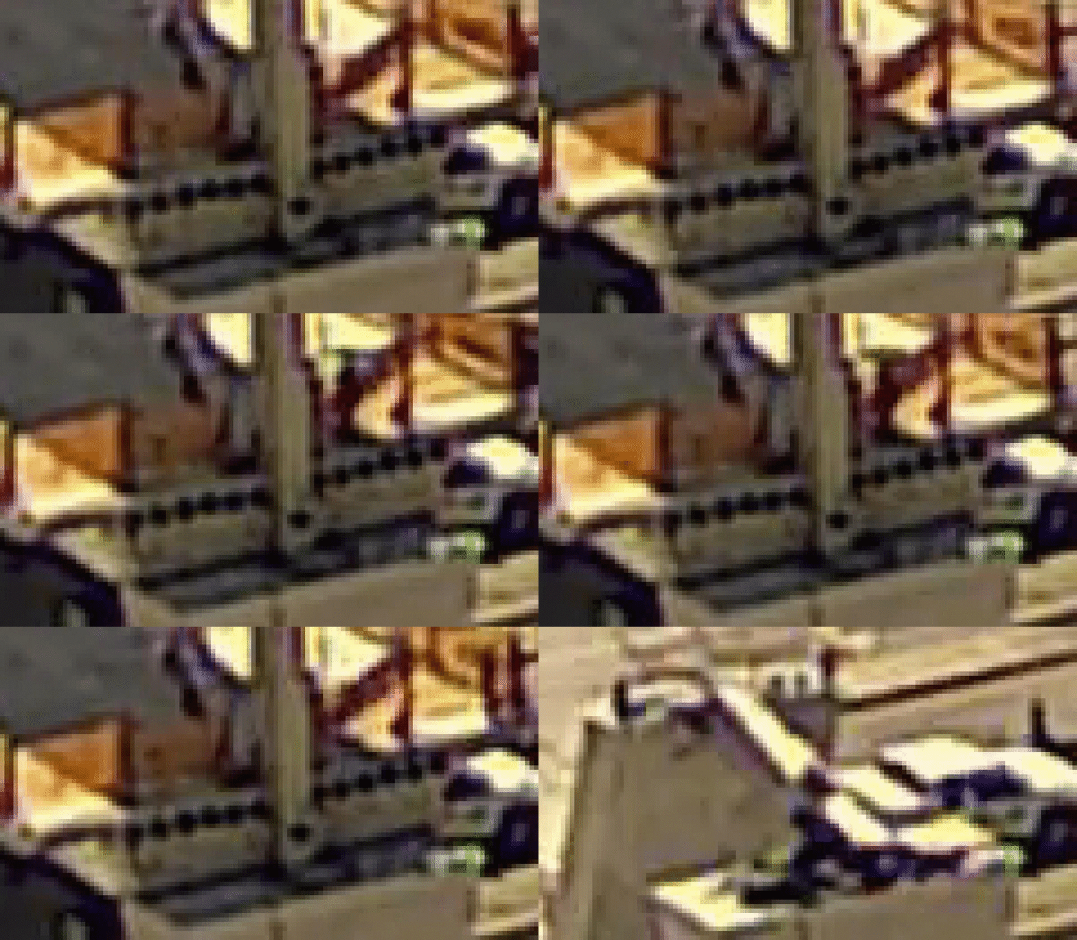
No interpolation, just enlarged pixels (Nearest Neighbor)

NN16x_Collapse_26414-26423_bzugzt.gif
 
Status
Not open for further replies.

Part and Inventory Search

Sponsor