OK - here goes.
The FIU Pedestrian Bridge is basically a concrete truss. It has the added complexity of being cast monolithically, albeit there were three basic phases to that casting. The deck was cast, then the diagonals, then the canopy. But the construction joints were intended to create a monolithic state. The diagonals were cast in one phase, and could likely be considered monolithic without conditions, provided they were cast quickly enough to prevent cold joints.
The “added complexity” of being monolithic creates the possibility of bending moments being induced in members by rotation of the joints. So while this structure is not a pure truss, I suspect the designers used a truss analysis to determine the axial forces in the members, and then checked or analyzed the effects of joint rigidity on the diagonal members. And I would concur with that procedure. FEA analysis may make the distinction a moot point and have included everything in one analysis. I think it would be appropriate to not reduce axial forces in members due to continuity, and the simple truss analysis should be used to determine primary forces in the members.
If it can be considered as a truss, here is a definition for that from Wikipedia:
“A truss is an assembly of beams or other elements that creates a rigid structure.[1] In engineering, a truss is a structure that "consists of two-force members only, where the members are organized so that the assemblage as a whole behaves as a single object".[2] A "two-force member" is a structural component where force is applied to only two points. Although this rigorous definition allows the members to have any shape connected in any stable configuration, trusses typically comprise five or more triangular units constructed with straight members whose ends are connected at joints referred to as nodes.
In this typical context, external forces and reactions to those forces are considered to act only at the nodes and result in forces in the members that are either tensile or compressive. For straight members, moments (torques) are explicitly excluded because, and only because, all the joints in a truss are treated as revolutes, as is necessary for the links to be two-force members.”
(Emphasis mine).
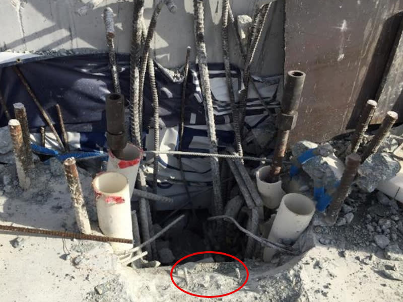
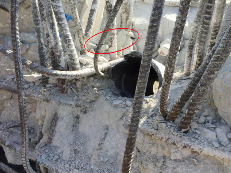
One dictate of “truss” design is to provide concentric loads at a joint. This eliminates eccentricity and minimizes (to zero if a true pin) bending and shears in the members. This is accomplished in the layout and dimensioning by passing the neutral axis (or line of action, or centroid) of all members thru the center of the joint. A primary benefit of this concept in a truss of the configuration at FIU is that the vertical components of web members are directly passed from tension in one member to compression in the adjacent member, without passing through another member. The PT rods and anchor plates pass thru to above the canopy and transfer their loads to the blister and canopy as a means of anchorage, and could cause rotation forces which must be supported by the canopy and blister. The downward vertical component of the PT force is considered to be resisted by the compression component of the other diagonal, applied at the center of the joint. The behavior of the joints with lapping PT rods anchored beyond the extremity of the compression member causes me a bit of concern. The compression forces under the PT anchor plates are intersected by the compression in the other member at different angles (depending on the joint). I am unsure about how well this creates an ideal truss joint.
From observing the detailing of this structure, the principal axis or line of action of the web diagonals in this structure seem to comply with this concept. One condition which may not comply with concentricity is the connection of the fake pipe “stays” which align with a diagonal but deliver a vertical load quite eccentric to some joints, but these loads were not in place at the time of the collapse. Vertical loads induced by the weight of the pipes would have been distributed to the joint thru moments in the blister and canopy.
In a horizontal parallel chord truss with joint concentricity, all vertical components of loads are resisted by the diagonals, Loads from above (canopy weight, pipe stays, live load) are considered applied directly over the joint. Tension in a diagonal passes thru the “work point” of the joint, with its vertical component added to the roof load from above and becomes the vertical component of compression in the adjacent diagonal at that joint. The horizontal components are transferred to the top chord (canopy in this case) as compression (increasing the axial force in the canopy or decreasing that force, depending on geometry and force vectors). With a horizontal top chord having only compression, there is no vertical component of that force in the chord which can provide vertical support to the truss. The top chord must carry its weight and tributary loads and deliver those loads to the joint while resisting the flange force in this structure.
With that said, technically, in the case of a simple truss, no diagonals “hang” from the top chord (canopy). They receive their vertical support from the joint. In this case, the canopy is above the diagonals, and while they may appear to “hang”, I do not think the designers intended that to be the case. The vertical component of member 11 would likely have blown thru the 12” thick canopy far more easily than it blew out thru the deck and diaphragm but it did not because member 10 restrained the joint 10/11, intercepting the vertical component of member 11 below the canopy.
It is not impossible to connect a diagonal of either tension or compression some distance from the center of the joint (the lines of action might intersect above the canopy, in such a case). Doing so would apply loads of several hundred kips in this case (lets think compression) to some point away from the line of action of the vertical component of the tension member, and induce serious shears and moments in the roof canopy. That can be dealt with in the design but would require special design and detailing of the canopy in that area. Thankfully the joints appear concentric in this structure.
Every piece of this structure is necessary for the success of this structure. If one element fails, it collapses. In that sense, the success of this structure “hangs” on the proper performance of every component. The canopy is one of the elements which must not fail.
As Ben Franklin said, “We must all hang together, ....“.
Comments expected.
Thank you.


