Continue to Site

Eng-Tips is the largest engineering community on the Internet

Intelligent Work Forums for Engineering Professionals

  • Congratulations KootK on being selected by the Eng-Tips community for having the most helpful posts in the forums last week. Way to Go!

Miami Pedestrian Bridge, Part XIII 81

Status
Not open for further replies.

JAE

Structural
Jun 27, 2000
15,444
A continuation of our discussion of this failure. Best to read the other threads first to avoid rehashing things already discussed.

Part I
thread815-436595

Part II
thread815-436699

Part III
thread815-436802

Part IV
thread815-436924

Part V
thread815-437029

Part VI
thread815-438451

Part VII
thread815-438966

Part VIII
thread815-440072

Part IX
thread815-451175

Part X
thread815-454618

Part XI
thread815-454998

Part XII
thread815-455746


Check out Eng-Tips Forum's Policies here:
faq731-376
 
Replies continue below

Recommended for you


So the deck surface delaminated about an inch below the surface in areas larger than the contact zone for 11 and 12.
I hope they at least hammer tapped the surface to establish the extent of that delamination thru sounding. Ultrasonic would be better.
I have to wonder if there was a problem in screeding the deck surface and more concrete was added at this area to make grade. That could have created a lack of aggregate across this zone, and created an unintentional pour joint. Bummer location.

Plenty to ponder here. Quite a release of docs. I see FIGG found the SF to be 1.25 for shear friction under 11 and 12, thus proving it should not fail. The overall SF for horizontal shear friction between webs and deck was more than 11. Good head fake there.
Much to digest.
Thanks for the link.

 
Still plowing through it. But one important aspect is that this new tranche of documents corrects a misconception delivered by an incorrect callout on one of the photos in the preliminary report.

In that prelim report, a callout refers to the lower PT rod in #11 as "sheared," implying that it had failed in shear during the collapse. However, the evidence of other photos and diagrams is that the rod was intact after the collapse, and had been cut after the collapse in the process of relocating key portions of debris for later use in the investigation.

New reports available in this docket correct that misconception by omitting references to the "sheared" PT rod, and including photos depicting it as intact.
 
The "sheared" comment was from OSHA. More concerned with people than flawless structural analysis.
 
Lessons will be learned from this tragedy. Hopefully, the victims' families will gain some comfort from that, along with at least some degree of monetary compensation.

I believe that two things are obvious: 1) Concrete truss design is complex, and should not be attempted without exhaustive research to establish the appropriate parameters, and 2) Shear friction as a concept needs a lot of work.
 
There are many photos I have not seen before.
I find pics # 71,88,89,90,92,and 93, plus #102 very revealing. Scary, actually.
My take is member 11 was in bad trouble and the base of 11 and 12 was outbound.
Also it appears the first hoop of #7 shear -friction reinforcing across the plane at the top of the deck was intact after the collapse. That reduces the contribution of the reinforcing. Apparently the south most hoop was in the fillet under #11 and did not share much shear load because the cracking in 11 was north of that hoop.
 
After seeing the collection of photos documenting the slow progression of collapse, it's hard to believe that of the many engineers involved, nobody realized the magnitude of what was happening. I believe I would have declined to even go on the bridge to take pictures.

Brad Waybright

It's all okay as long as it's okay.
 
thebard3 said:
..declined to go on the bridge to take pictures.

Me too.

After reading some of the docket, it appears parties involved were right and correct, yet wrong. (edited - don't want to go there)

I think the bridge was so massive, they did not feel it could collapse from little cracks. I have severe fear of heights, yet I can look out airplane window with no worries, yet I sweat profusely on a 16 foot ladder.


I feel following link is most interesting. The illustrations inspire me.

Bridge Factors Attachment 73 – FHWA Assessment of Bridge Design and Performance
 
Ok, here's something that has puzzled me for a long time on this bridge.

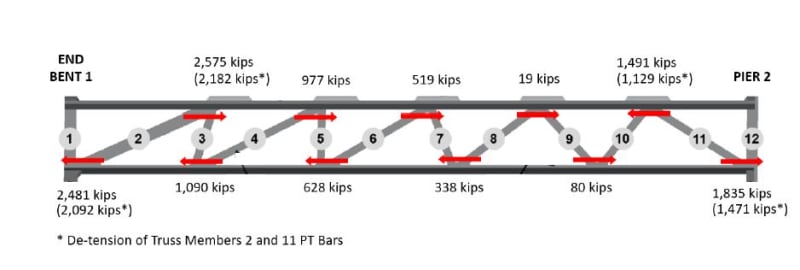
The picture below shows, to me at least, a large discrepancy in resisting forces on the top and bottom chords.

I.e. the top chord has a lot more force going right and the bottom a lot more going left. In a classic truss design these forces are roughly equal.

But here we have large discrepancies (about 2000 kips) which I don't see being taken into consideration anywhere. The rather puny columns at the end aren't going to resist anything much so where does all this out of balance force go?

I know this is a simplification and that the truss was supposed to be rigid, but this really doesn't look to me that these out of balance forces are being accounted for. But then I'm not a civil design engineer, but I would like to know what is happening here.

bridge_force_akd0vm.jpg


Remember - More details = better answers
Also: If you get a response it's polite to respond to it.
 
jrs_87 (Mechanical)9 Oct 19 12:35 I feel following link is most interesting. The illustrations inspire me. Bridge Factors Attachment 73 – FHWA Assessment of Bridge Design and Performance [URL unfurl="true" said:
https://dms.ntsb.gov/pubdms/search/document.cfm?do..[/URL]]
Thank you for prompting me - I immediately went there and I find it interesting also.
I am struck by the clarity of the presentation in this document. Compliments to the authors. It is easily understood.

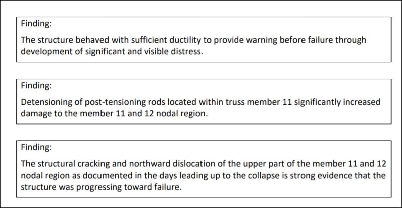
I find this part interesting - and damning to those at the March 15 meeting. From page 66 of 90.
FIU_FindingsPg66of90_twyfwz.jpg


Many items are eerily similar to points and illustrations previously presented in this forum. Kudos to all.
 

I see what you are seeing.
Where does that diagram originate? I think I have seen it but do not recall.
I can't believe that everything from the south end adds to a value at node 10/11. The arrows seem to show the horizontal shear from the diagonals but I am not sure.
Are they superimposing the PI forces?
Thanks,
 
I agree with your comment about victims and families.
My thoughts as to shear friction - it seems that 1) there was no preparation of the construction joint area at the deck surface which would have required more steel across the joint; 2) the cracking of Diaphragm 2 from vertical load severely reduced the capacity of any steel in member 12 to contribute and that reinforcing should not have been considered as contributing; 3) that same cracking of the diaphragm reduced the punch out capacity severely; 4)as discussed here before and by FHWA, the clamping force from transverse PT was overestimated; 5)leaving the need to provide enough reinforcing across the construction joint to resist all loads, which was not done (woefully inadequate amount provided); 6) the FHWA report discusses cohesion, which FIGG properly disregards, and was lost before the bridge was lifted by the transporters - the first cracking is evidence of loss of cohesion.
My takeaway is that with another half yard of concrete and half ton or ton of reinforcing at node 11/12 and node 1/2, and with proper joint preparation, the bridge would be standing today. There may be other problems yet undetected, but it would not have failed on March 15, 2018.
And there is much yet to be learned.
Thanks for the opportunity to comment.

 
The diagram came from the link in the post above mine - Attachment 73.

Remember - More details = better answers
Also: If you get a response it's polite to respond to it.
 
Thank you. I do not think that is correct. I do not see how node 8/9 can have so little shear transmitted to the canopy. Must be something to do with elastic changes in dimensions - they found similar numbers 4 times, though the last one was a bit more reasonable. Could this be the effect of elastic shortening from PT in the deck?
The simple truss analysis of years ago assumed things were rigid members with pinned joints. Reality can be different.
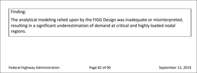
The killer "Finding" ----------
FIU_Findings_Pg_82_ajw4tl.jpg


I do not comprehend the difference between FIGG calcs and the NTSB results - - anyone???
Surely FIGG will have a comment.
In a previous post I had said "There may be other problems yet undetected" - this may be one of them. If the NTSB report is correct March 15 may have been the most fortunate date available.
 
I haven't read it all, but did anyone find mention of bending/frame action, and also axial shortening in the top and bottom flanges due to both shrinkage and PT?
 
hokie66 (Structural)9 Oct 19 21:51
I haven't read it all, but did anyone find mention of bending/frame action, and also axial shortening in the top and bottom flanges due to both shrinkage and PT?
The solid modeling software should address fixities at joints, but I have not read any conditions of that nature.
The Feds ran 4 runs and got different answers each time - by maybe 10% - maybe more.
Strikes confidence in me.

 
Have done some work outside - had time to think.
End vertical reactions are pretty much equal. Member 2 is much flatter angle than 11, so there is a greater horizontal component thrusting into the canopy and pushing on the deck than at member 11.
So it appears that to balance shear loads to the canopy we take node 2/3 at 2182 kips AND ONLY 464 kips northbound at node 4/5 for a total of 2656 kips and that will balance all the remaining shears pointing southward. So the arrows are backwards on several nodes.
Am I not corect?
Same idea for the deck. And arrows are pointed the wrong way there too.
I am basing this on a free body of the canopy - horizontal forces into the canopy must balance to zero or the canopy will wind up in Sweetwater.


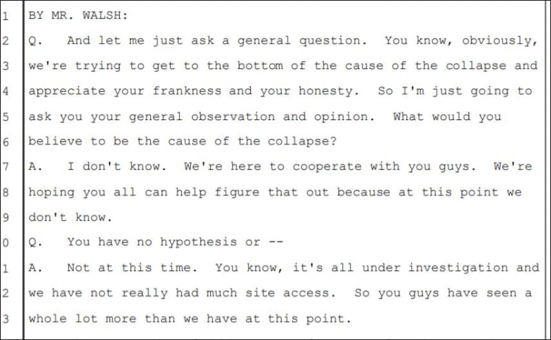
Quote of the week - or year - -
"I don't know".

Interview of EOR March 20, 2018.

FIU_Pate_Depo_pg256._JPG_h2c3z4.jpg
 
One of the supporting documents submitted by Figg is this Party Submission:


...which includes Figg's own "probable cause":

Figg said:
The FIU University City Prosperity Pedestrian Bridge construction accident occurred because the construction joint at the north end of the main span between the truss members and the bridge deck was not roughened as required by the Florida Department of Transportation (FDOT) Standard Specifications for Road and Bridge Construction. This failure to meet the construction specification requirements was not noticed by either the contractor’s quality control personnel or by the construction inspectors under contract to FIU.

Um, yeah, good luck with that.
 
Figg's submission is actually very well done considering. ( ) They make several good points, I will not cite any here, check yourself please. However, I reject their concept of redundancy. And Figg seems prone to wing-it excessively, even though they possess advanced skills.
 
Status
Not open for further replies.

Part and Inventory Search

Sponsor