Nodal Shears FHWA analysis of FIGG design - Bridge Factor Attachment 73 - pg 77 and 78 of 90
Bridge Factors Attachment 73 – FHWA Assessment of Bridge Design and Performance
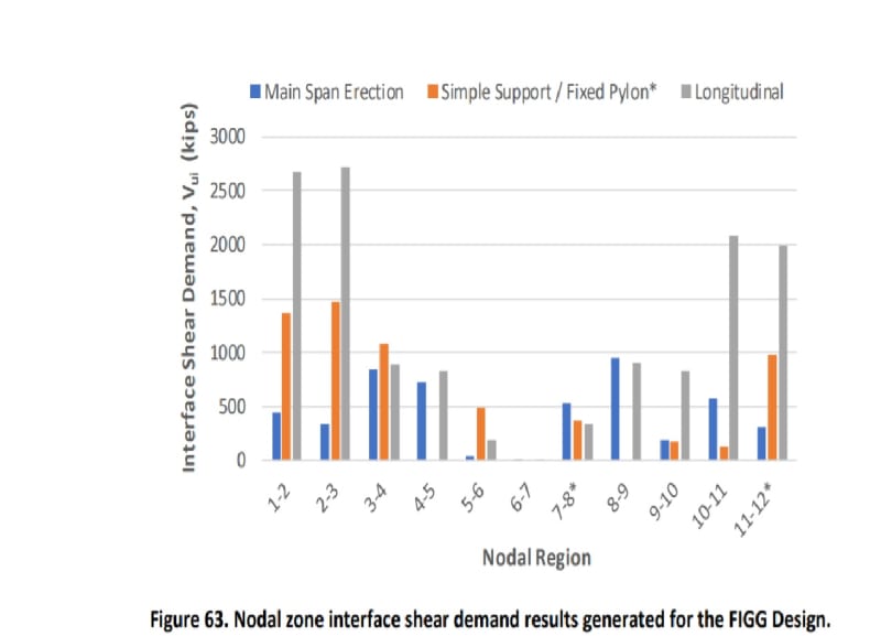
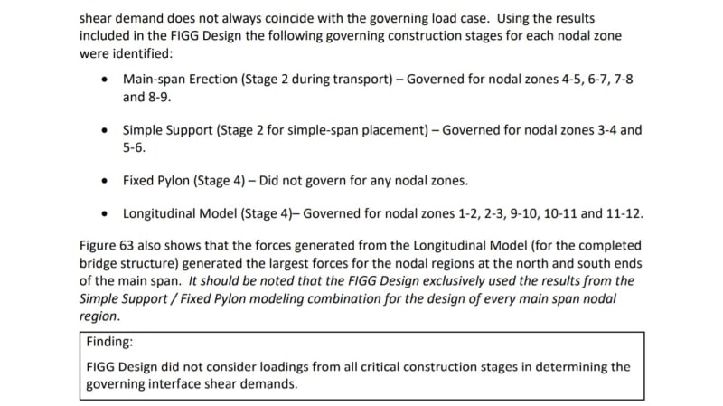
FHWA finds FIGG underestimated nodal shear demand at 11/12 and deck. FHWA represents FIGG calculations as showing shear at 11/12 to deck to be twice as great (approx) under full two span condition than when under single main span with full fixity at the pylon/pier (north end of main span), and the greater value should have been used for design and was not. Both conditions are noted to be Stage 4.
Note the Fixed Pylon (Stage 4) is an intermediate construction stage subject to construction loads only. Failure prevented this condition from being encountered.
Note also that the Longitudinal Model (Stage 4) is also an intermediate condition subject to construction loads only.
I do not see how it is possible for moments at the north end of the main span to be greater than when full fixity is assumed at that end. Unless one condition is unfactored DL only and one is full factored DL and LL.
First, DL is about 11 kips/ft and LL is 90#x30 feet = 2.7 kips/ft. Factored that is 11k X 1.25 = 16.75 kips/ft DL and 2.7 k X 1.75 = 4.37 kips/foot factored LL for a total of 18.5 kips/ft factored load. The factored TL load is 1.67 times unfactored DL. So the 2X increase was not from considering unfactored DL vs factored TL. Factors are FHWA representation of those used by FIGG.
The only way I can see the shear demand in node 11/12 to deck increasing beyond that from full fixity at the pier is if enough negative moment is created over the pylon by the continuity PT in the canopy to draw even more load from the main span to the pier. But that condition is Stage 5, after the north span has cured.
So I am confused as to how FIGG could have had such a discrepancy between shear demand at node 11/12 to deck under Fixed Pylon (Stage 4) vs Longitudinal Model (Stage 4) conditions.
As I recall prior discussion here the unfactored DL shear at node 11/12 to deck was in the order of 1300 kips. Or was that the axial load in 11? Adding LL and factoring the loads by the 1.67 from above (DL to Factored TL ratio) yields 2170 kips - pretty much what the graph by FHWA shows for 11/12.
Perhaps FHWA is misinterpreting something also?
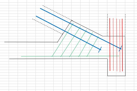
Whatever the answer, this points out the complexity of this design and the various support conditions which existed - full form support, full span at casting yard, intermediate span during transport and reversal of loads in many members, and final support in place. All happening in a brittle structure.
And if the non-redundant factor is only 1.05, that would not have saved this structure at this phase.

")