Shear Friction issues.
This was previously posted and deleted so I could clarify items. Here it is again.
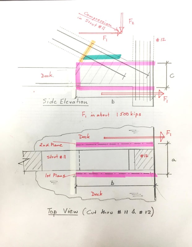
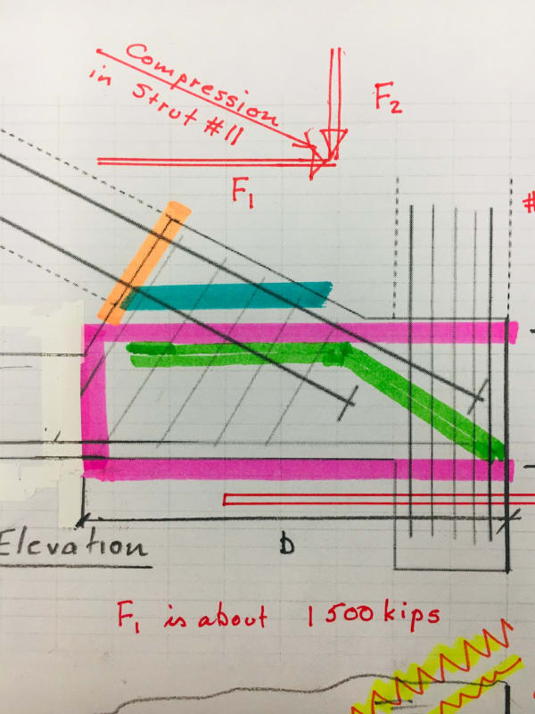
The subject of clamping force on the sides of the assumed shear plane where 11 and 12 punch thru and out the end of the deck is interesting to me. The conditions surrounding this failure provide an opportunity to examine the concept of shear friction. I would like to discuss, hopefully not alone, the shear friction concept as it could apply to a "clean" version of the FIU bridge, north end of main span.
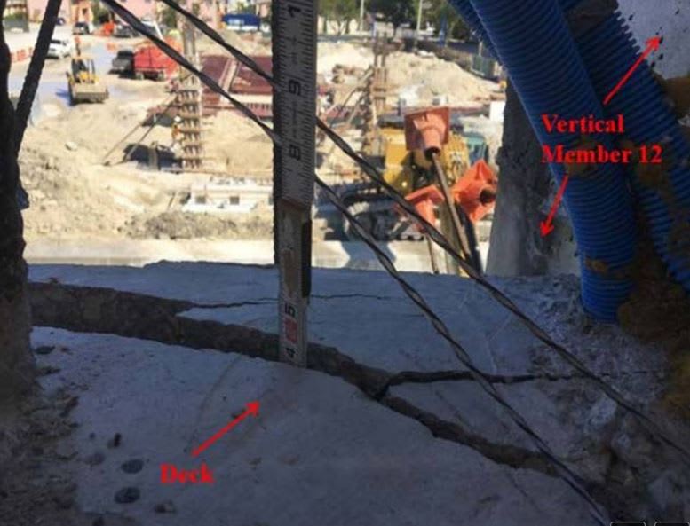
The conditions at hand are certainly not 'clean' as this was a multi phased failure with prior cracking at the deck surface for one zone, failure plane defined by the void created by the lower PT duct in member 11, the presence of 4 - 4" dia pvc ducts, proximity to the end of the structure, and presence of already cracked end diaphragm 2, to list a few.
If this were to have occured in an area of deck fully surrounding the zone, it would have been much like a column in a flat slab. Failure would be mostly in diagonal tension and be reinforced for that. Portions of this failure developed into diagonal tension as it neared the edge or end of the deck, and that zone was already cracked by the load in the diaphragm. The diaphragm cracking may have loosened things up for the blow out - or maybe the other way around.
For for discussion and clarity, I would like to just discuss the shear friction issue. My purpose is not to declare some concept as the final thoughts but rather to elicit discussion and consideration of conditions unique to a simplified modeling of this failure. There are many present here with experience, understanding, and inquisitive natures with much to contribute. I hope something in this will interest you.
If reinforcing steel across the shear friction plane can provide shear capacity because it goes into tension and that is measured by 0.9 times yield or 57,000 psi lets see how much stretch that requires to develop 57000 psi (or whatever - the principle remains). Using a #7 bar and development of maybe 24D = 1.12"X24 =27 inches. If tension in the steel is zero at the embedded tip and 57,000 psi at the interface, the average is 28,500 psi and stretch is 28500X27/29,000,000=0.026 inches on one side. Then if the same embedment stretch develops in the other side of the interface there is a total of 2X0.026=0.052 inches gap in the interface at full factored resistance.
Of course if the surfaces have separated by 52/1000 of an inch we can now disregard any cohesion contribution.
I suspect the actual development length is less than that required by code, so lets say it actually develops fully in 12 diameters, so the stretch is half that just calculated, or total gap = 0.026 inches.
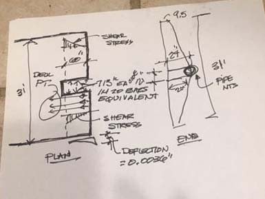
For the specific but simplified condition at hand, consider the deck as a monolithic flat member that is 31 feet wide, thickness varying from 9.5 inches at edge to 24" at center with a notch cut out for members 11 and 12. That notch is about 21" wide and 60 inches in length measured from the end of the deck and goes all way through. And lets consider that 25 total sq inches of reinforcing should cross the two interface planes if we cast the notch then pour members 11 and 12 into that notch and try to push them thru. We will adjust for monolithic vs intentionally roughened vs as cast conditions after the concept is defined, which I hope is about now.
So to support aggregate interlock in the two planes each side of the 21 x 60 notch, with those planes being 24" x 60" each, we can provide 12.5 sq in of reinforcing crossing thru each side. That reinforcing can allow - in a two part isolated shear plane condition - a gap of 0.026 inches and still function as a shear friction joint. (according to codes).
But lets disregard any steel and just let the shear capacity of the deck on each side of the notch provide resistance to the movement which would have stretched the steel across the assumed shear planes by 0.026 inches.
12.5 sq in of steel at 57 ksi is 713 kips each side. Average thickness of the deck each side of the notch is (24+9.5)/2 and 14 feet long from notch to edge of deck and that is 16.75" avg X 14'X12= 2800 sq inches. The shear stress in that section from the equivalent 713 kips is 713000/2800 =255 psi. It varies from 0 at the edge to 255 psi at the end of the notch, 60 " from the edge. Shear deflection at the edge will be tne average stress X length of loaded section (60") /Ev of 0.4X5,300,000 or 255/2X60"/(.4X5300000) = 0.0036 inches. That is about one seventh (0.14) of the stretch in the reinforcing which would cross the plane and still meet shear friction design concepts.
There is no active clamping force in this zone because the transverse PT begins just south of the cut out notch zone we have defined. And the shear deformation in the protruding flanges is zero at the end of the notch where the deck is 31 feet wide without a notch. So the average deformation from this spreading shear is far less than the stretch required to produce tension in the cross plane reinforcing. The longitudinal deck PT crosses the plane in the deck at maximum "spread shear" at 60 " from the end so bending moment in the protruding flange is negligible and the shear deformation is the major factor. That longitudinal PT provides an active clamping force for the shear in the deck extensions.
So the questions that arise include:
1) If passive reinforcing across a defined or assumed shear plane can provide shear resistance by developing or retaining a condition of restrained contact and thereby contribute to shear capacity of that plane, can other conditions which create similar restraint contribute also? And if not, why is the reinforcing allowed to do so?
2) Should bar sizes across a defined plane of shear friction be limited in size? Smaller bars develop full capacity in shorter lengths and therefore the stretch is less.
3) If developing the tension in the reinforcing across an actual created joint causes stretch in that reinforcing (I see no other way) with some corresponding separation of mating surfaces, why is cohesion even considered to act in conjunction with the reinforcing?
4) Is the shear friction design based more on formulas which attempt to define what was learned in test results and less on engineering logic? (Dare I challenge the gods?)
5) Is something bad wrong with my logic or calculations? This should be a gimmie - hint: Very probably.
Thank you. I would really appreciate comments.