Continue to Site

Eng-Tips is the largest engineering community on the Internet

Intelligent Work Forums for Engineering Professionals

  • Congratulations KootK on being selected by the Eng-Tips community for having the most helpful posts in the forums last week. Way to Go!

Miami Pedestrian Bridge, Part XIV 78

Status
Not open for further replies.

JAE

Structural
Jun 27, 2000
15,460
A continuation of our discussion of this failure. Best to read the other threads first to avoid rehashing things already discussed.

Part I
thread815-436595

Part II
thread815-436699

Part III
thread815-436802

Part IV
thread815-436924

Part V
thread815-437029

Part VI
thread815-438451

Part VII
thread815-438966

Part VIII
thread815-440072

Part IX
thread815-451175

Part X
thread815-454618

Part XI
thread815-454998

Part XII
thread815-455746

Part XIII
thread815-457935


Replies continue below

Recommended for you

FortyYearsExperience (Structural)

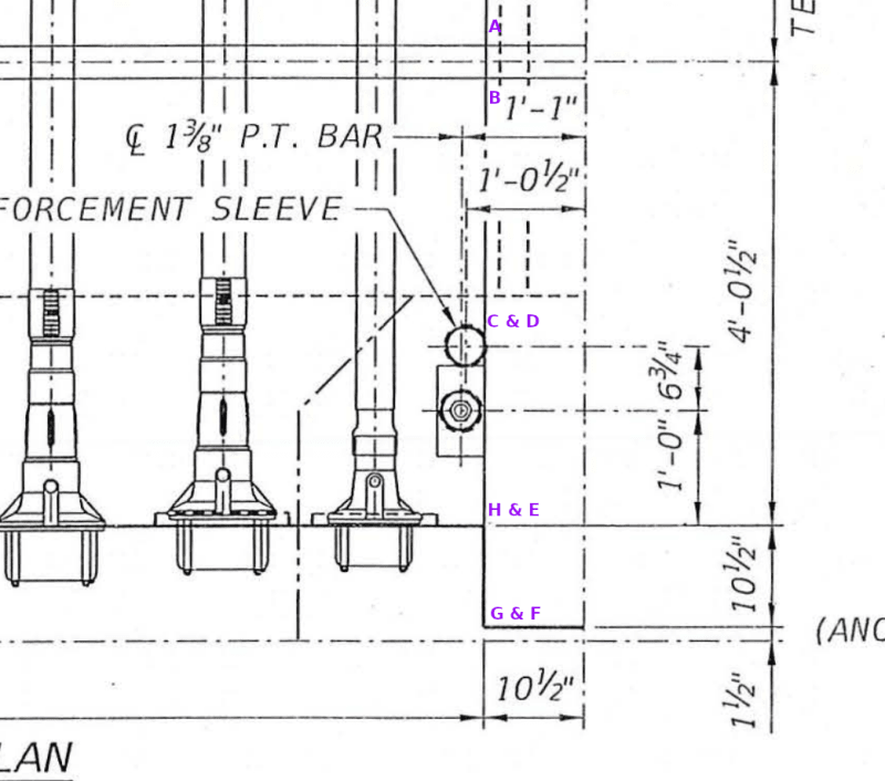
A plan view as requested
Plan_of_11_ans_12_annotated_wethyp.png
 
FortyYearsExperience (Structural)

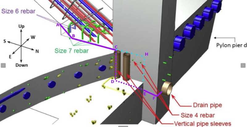
Also a 3D cutout view (originally from NTSB Final Report Fig 16)

3D_11_12_and_deck_annotated_bslunl.png


Please note area bounded by C-D-E-H is the East face of Member 12 bonding with the deck. It has an identical West face at the back of member 12.

The flaw of the design is that along the East/West direction the longitudinal tendon anchors, shown in purpose, prevent placement of rebar linking Member 12 with the either side of the deck. The two size 4 bars, shown green in BTSB 3D sketch, were the only reinforcement.

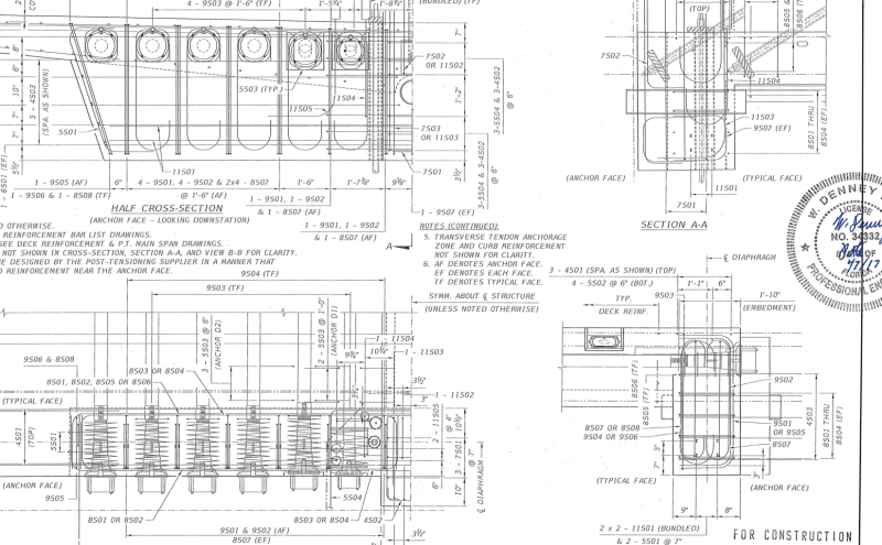
In the South/North direction it is also impossible to place large rebar to link Member 12 with the deck because the obstruction by the two PT rod anchor plates.

obstructions_mhekym.png


The devastating effect of the two 4" vertical sleeves, extending to the full depth of 4'-3.875" of the diaphragm, on either side of Member 12 should not be overlooked. Their presences and locations served as a partial isolation joint between the deck and Member 12.

The positions of the two PT rod anchors can also be significant when examining the NTSB Fig. 32. It could be seen while the re-tightening of the lower PT rod could progressively compress the deck against the 11/12. The similar re-tightening of the upper PT rod, on the other hand, could encourage the concrete to debond along interface D-E-F which at the thinest point is only 6.2" wide on either side of the 8" drain pipe.
 
I may be missing the question here, but does there have to be an actual vertical shear plane, in this case? It is my understanding that this structure is primarily a warren truss with some minor frame action due to the joint construction. As such, the vertical load of the truss is delivered to the support by an axial force in the diagonal web member ending over that support. The vertical reaction of the truss is supported by the vertical component of the axial load in that member. In a true truss, and with that diagonal member not being vertical or horizontal, there is a corresponding horizontal component of that axial force. When the joint fails horizontally and no longer resists the horizontal component of the axial force in the diagonal, the vertical component is lost also. Thus a horizontal failure results in a loss of vertical support.
I do not see this failure as being significantly different had there been an intentional slip joint, perhaps in the form of teflon pads, at the surface of the deck with Members 11 and 12 sitting on it and no reinforcing passing thru the joint. There would not have been a vertical shear plane. There would have been failure due to a lack of resistance to the horizontal component of any axial load in Member 11, preventing the development of any axial load in Member 11 EDIT ADD and therefore preventing any vertical component to support the structure.
It would have happened long before transporting and likely during removal of falsework. Actual joint construction, reinforcing, and post tensioning simply prolonged the event until 1:46 PM, March 15, 2018.
 
Compressing the deck against 11/12 could be a good thing because it could generate additional clamping force for shear friction and thereby increase the joint capacity in shear. But that is not all the lower PT rod does when tightened. While it compresses the deck against 11/12 it does so because its tension force is delivered to member 11 as compression at the top of the canopy and is then delivered by Member 11 to the deck at the 31 degree angle, therefore it has a greater horizontal component in shear than a vertical component to compress. So retensioning the lower PT rod was not a good idea either. The lower PT rod was adding shear faster than it was increasing capacity.
The same thing could be said of the upper PT rod until Member 11 and the joint to Member 12 began to split. Until that point both PT rods were adding shear more than clamping compression, and instead were contributing to the cracks in the deck around Node 11/12 and the pvc sleeves. After member 11 split and the joint began to disintegrate, the failure was underway.
It could seem that the EOR found advantage in the low angle of Member 11 and sought to restrain the failure evident in the deck using the horizontal component of that added/restored PT force. It could maybe have worked if the upper end of Member 11 were fixed to some immovable object, but instead Node 10/11 just reversed the force and pushed back on Node 11/12.
I have yet to distinguish in my mind between whether the splitting of Member 11 happened before or after or during the shear failure of the deck block beneath Members 11 and 12 and between the 4" vertical sleeves and above the 8" drain sleeve.
Thank you for your discussions.
 
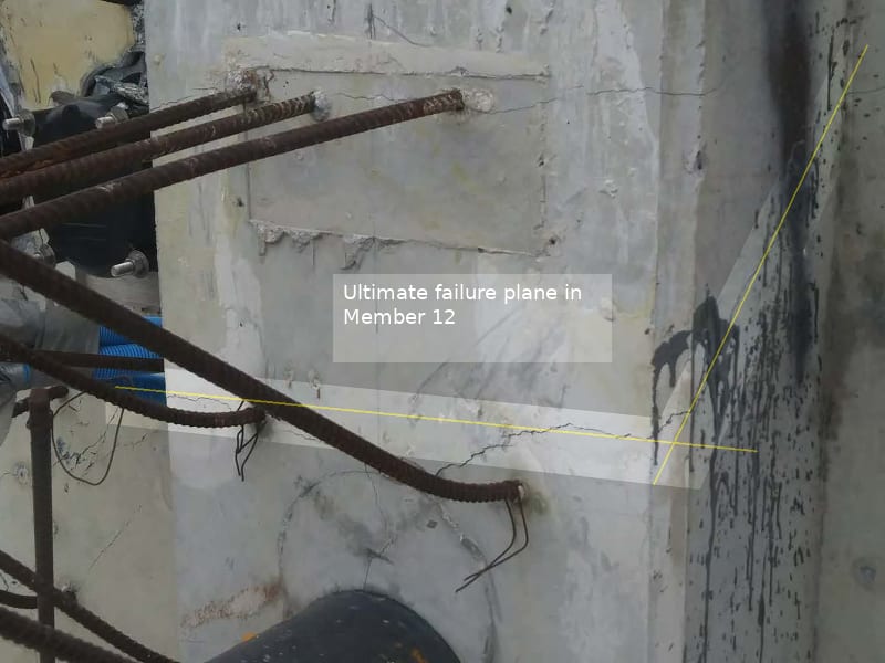
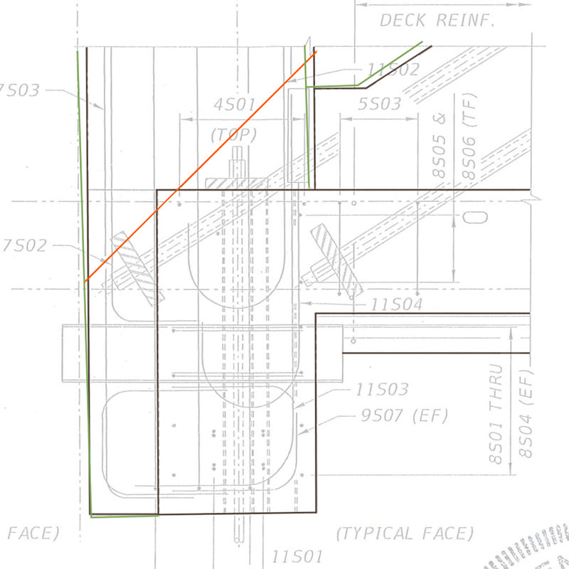
Upon closer inspection of what I suggest is the ultimate failure plane through Member 12, I realized that it does not follow the trajectory of the upper PT rod in Member 11 but rather it is the 45 degree shear plane of Member 12, which is relatively fixed at each end but not fixed to the slab. Thus, the collapse occurred when Member 11 ultimately broke the back of Member 12 which was forced to act as a buttress to Member 11.

A trace of the crack in Member 12 from just above the lower slab rebar at the north face of 12 to just below the upper slab rebar at the north face of the deck reveals this possibility.

Ultimate_fialure_plane.02_m2onow.jpg


Ultimate_Failure_of_Member_12_qyxnbj.jpg


Edit: To clarify, Member 12 had to allow Member 11 room to move north. The shear plane in 12 was the weakness that was exploited but once enough northward movement had occurred, Member 11 failed just above the nodal block to start the cascade. The falling deck rotated the diaphragm off of the base of 12 while 11 hammered into the node. I believe that this sequence allows for the deformity in the upper PT rod in Member 11 to occur while the lower PT rod kinks at the slab.
 
Sym P. le (Mechanical) said:
To clarify, Member 12 had to allow Member 11 room to move north.

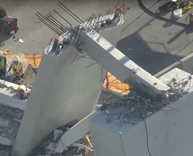
The above postulation does not appear to be supported by the collaspe photo shown below. It is clear that after collapse the end of 12 was resting on the top of the North pier. Had 12 been allowed 11 to move north by shearing off as claimed then 11 had be further north of 12 but it ended up below and on the south side of the pier.

The second weakness of the postulation of 12 shearing off is that the shearing plane can only take place when 11 was moving but 12 did not. This is impossible because during the collapse a hinge was seen at 10/11 connection with the canopy. Thus the triangle formed by 11, 12 and the canopy was initially rotating as one entity and there was an absence of force available to shear off 12 within itself. Remember once in motion the bridge was a mechanism.

Member_12_after_collapse_nkbyz7.jpg
 
Vance Wiley (Structural) said:
While it compresses the deck against 11/12 it does so because its tension force is delivered to member 11 as compression at the top of the canopy and is then delivered by Member 11 to the deck at the 31 degree angle, therefore it has a greater horizontal component in shear than a vertical component to compress.

This can be confusing as I was initially thought it too. But I now believe the stressing inside 11 does not increase the horizontal shear in the system.

The easiest way to explain it is to imagine the 12 is prestressed similarly by a PT rod. While the compressive stress inside 12 is indeed increased the reaction will not be increased and the north pier would not feel anything. Thus by similar argument there should have no increase in the horizontal shear in the 11/12 joint by the PT rod re-stressing simlpy because 11 was inclined at 31 degree.
 
11 was separated from the deck at the time of re-stressing and the lower rod spanned the break. If I wanted to jack 12 out of the deck that's an arrangement that I'd say would work.
 
saikee119 (Structural) said:
I now believe the stressing inside 11 does not increase the horizontal shear in the system.
The easiest way to explain it is to imagine the 12 is prestressed similarly by a PT rod. While the compressive stress inside 12 is indeed increased the reaction will not be increased and the north pier would not feel anything. Thus by similar argument there should have no increase in the horizontal shear in the 11/12 joint by the PT rod re-stressing simlpy because 11 was inclined at 31 degree.

The force from internal PT in Member 12 which you describe would be perpendicular to the deck surface and therefore have no horizontal component. Member 11 is 58 degrees from perpendicular and has a serious horizontal component which must be resolved at the surface of the deck.
Of course the north pier would not feel anything - the reaction of the structure does not increase because the PT forces were internal to the truss and anchored in the deck which is a part of the truss. The PT forces were present in the truss while the truss was transported and erected in place. The pier is not a part of the truss.
l
 
Vance Wiley (Structural)

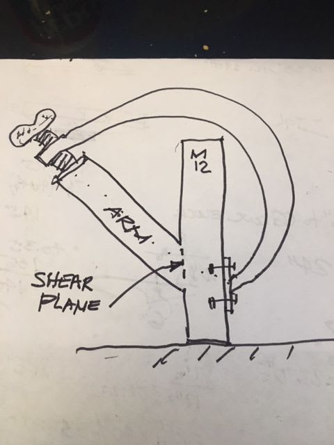
How about imagining just 12 on its own but with an arm sticking out at 31 degree. You can stressed this arm with PT rods as much as you want and it would not affect 12.

Another way is to imagine if you have a flat equilateral triangle on the ground each side is like Member 11. By post-tensioning one side internally with PT rod you will not get the remaining two sides stressed to the same level. The post-tensioned side will shorten axially in responding to the PT rod stress but the other two arms will simply bend slightly inward to accommodate the exial shortening of the first side. So the internal post-tensioning is not additive to the summation of forces at a nodal point in the equilibrium calculation. That would be my interpretation.
 
The lower end of the lower rod was not in member 12. It was in the separately cast deck. This is what the FIGG engineers missed.
 
3DDave

FIGG couldn't Cast the lower PT rod any further into Member 12 as it would interfere with the 8" drain pipe. FIGG also can't change the drain pipe position as the drain connects to two spans and datum sensitive for gravity discharge.

On hind sight one should have fought the architect, who most probably would say the new arrangement looks ugly, and route the drain sideway, not penetrating into the diaphragm at all but attached to its external face and do the same for the short span. A few extra meters of PVC drians readily discharge to the river down below would have bought the FIU bridge a new lease of life by extending the low PT rod fully into Member 12.
 

If the arm does not bear on the support below, the same problem exists at the face of the column. In this case the sliding force is vertical. On March 15 the sliding force from the PT was horizontal.
Here is a Member 12 with an arm and prestressing. If the acute angle between the arm and Member 12 is "A" it is my opinion the shear at the dotted "shear Plane" on the side of M12 is Clamp Force (PT) * cosine A.
FIU_M12_Clamp_yt2wjv.jpg
 
Vance, that's a great diagram and does not in any way represent the bridge in question.
 
saikee, the lower rod was not in 12 at all. The casting of 12 also stopped at the surface of the deck with the same cold joint as 11.

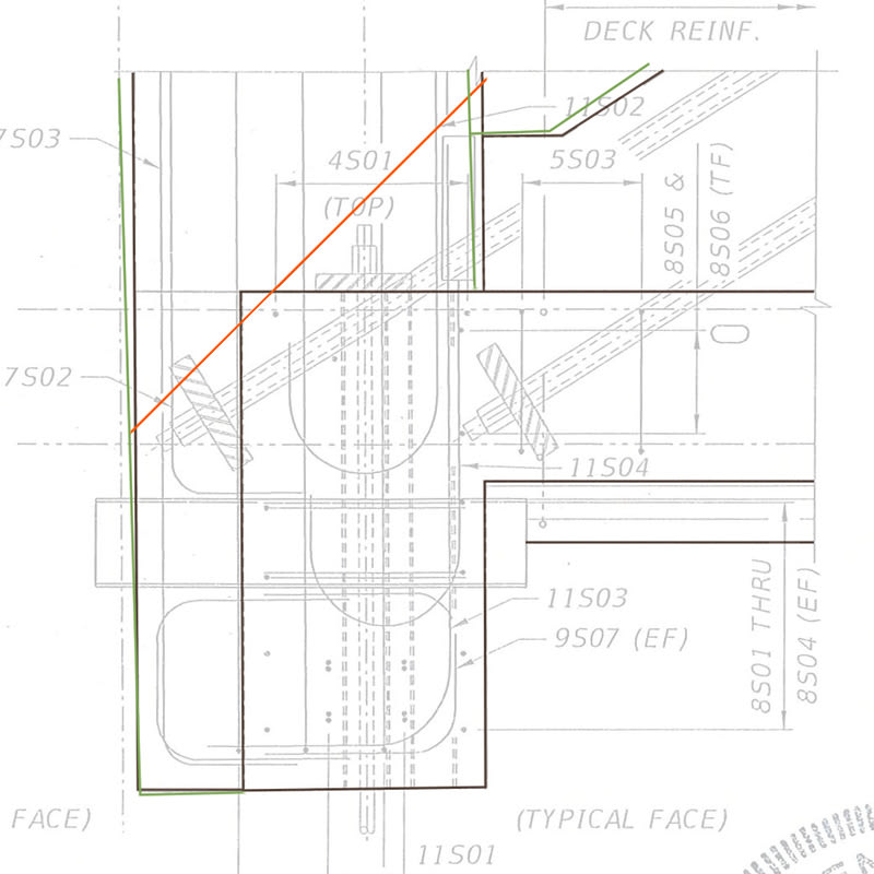
Ultimate_Failure_of_Member_12_qyxnbj_1_hknssm.jpg
 
Would neglecting the shear in the "shear plane" make it more relevant?
 
Vance, trace over the diagram I copied from the post by SymP.le and you wlll see there shear plane is between 11 and the deck, not between 11 and 12 and that the lower end of the lower post tension rod is in the deck and not in 12.
 
The force between the top end of the lower PT rod acts to force the 11/12 joint horizontally away from the deck.
The force of the lower PT rod was acting against the deck not against member 11.
The force exerted by the lower PT rod was trying to open the crack rather than pull it together.
The concrete had already sheered and shifted.
Only the re-bar was holding the joint together.

Bill
--------------------
"Why not the best?"
Jimmy Carter
 
3DDave (Aerospace) said:
Vance, trace over the diagram I copied from the post by SymP.le and you wlll see there shear plane is between 11 and the deck, not between 11 and 12 and that the lower end of the lower post tension rod is in the deck
Oh, I know - I am still chuckling about your response. Thank you for the compliment.
I was responding to " imagining just 12 on its own but with an arm sticking out at 31 degree. You can stressed this arm with PT rods as much as you want and it would not affect 12."
My concern is there seems to be a thought that the PT force does not have anything to do with shear at the top of the deck.
Hopefully I am just misunderstanding the points being made.
Thank you for your comment. I will hand it off to you for further comments.
 
Has this been considered?
Once the crack had opened up, the concrete had failed and the re-bar had started to deform.
Why did the crack stop there and not progress further?
The lower PT rod was acting as a restraint.
It had some freedom of movement inside the sleeve.
When the PT bar was tight against the bottom of the sleeve, the movement ceased.
The PT bar was acting as a restraint.
As the PT rod was tightened further, the force against the bottom of the sleeve in member 11 increased.
The concrete had already fractured and the rebar had deformed and was supplying minimum restraint.
At this point the structure was held together by the lower PT rod by reason of the downward pressure against the sleeve and the lower part of member 11.
I suggest that the first part of the final failure was the PT rod ripping out of the bottom of member 11.
So, the construction joint 11 fails and the 11/12 joint shifts until it is restrained by the lower PT rod and the compromised re-bars.
Then the tension on the lower PT is increased.
The lower PT rips out of the bottom of member 11.
No longer restrained by the lower PT rod, the 11/12 joint blows out away from the deck.
The damage to the ends of members 11 and 12 is subsequent to the failure of the bottom of member 11 and was a result of the failure of the bottom of member 11, not a cause of the failure.
I have not seen any mention of the restraining action of the lower PT rod once the concrete joint had failed.
Forgive me if I have missed something.
Bill
--------------------
"Why not the best?"
Jimmy Carter
 
Status
Not open for further replies.

Part and Inventory Search

Sponsor