Eng-Tips is the largest engineering community on the Internet

Intelligent Work Forums for Engineering Professionals

  • Congratulations waross on being selected by the Eng-Tips community for having the most helpful posts in the forums last week. Way to Go!

Miami Pedestrian Bridge, Part XIV 78

Status
Not open for further replies.

JAE

Structural
Jun 27, 2000
15,433
US
A continuation of our discussion of this failure. Best to read the other threads first to avoid rehashing things already discussed.

Part I
thread815-436595

Part II
thread815-436699

Part III
thread815-436802

Part IV
thread815-436924

Part V
thread815-437029

Part VI
thread815-438451

Part VII
thread815-438966

Part VIII
thread815-440072

Part IX
thread815-451175

Part X
thread815-454618

Part XI
thread815-454998

Part XII
thread815-455746

Part XIII
thread815-457935


Replies continue below

Recommended for you

Sym P. le (Mechanical) said:
The whole of your vertical plane CDEH has virtually no connective value, the result being that Member 12 becomes a vertical beam which 11 is pushing against.

There are several pre-existing design arrangements which weaken the connectivity of area CDEH. Amount them are :-

If you look at the area CDEH of NTSB Fig 32, available in 7 Jul 20 16:24 post, you will find the 4" vertical sleeves have taken up more than 50% of the available surface. The imposition of the sleeves displaces the concrete making locally insufficient amount to grip the reinforcement. The thin concrete layers between the sleeves and the rebar could break easily and trigger the bond failure of the whole bar.

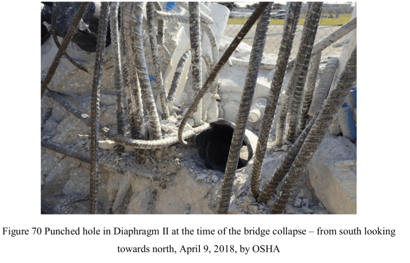
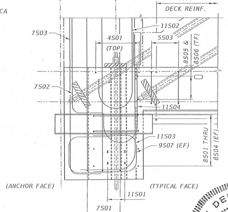
The area around the vertical sleeves is congested with reinforcement too making even less concrete to bond the reinforcement. You can see from OSHA Fig, 70 for yourself.
F70_z15vxg.png


The stress direction inside 11/12 is significantly different from the deck. The deck is uniformly post-tensioned by tendons both longitudinally and trasversely except the plan area of 11/12. Once the deck was post-tensioned the south portion of 11/12 could be influenced by the D1 tendons on both side of Member 12 but the rear of 11/12 was not stressed. Then when the PT rod stresses were applied the strain direction was about 31 degree to the horizontal. Thus area CDEH is the interface of two highly stressed zones each pulling it own direction. This explains why the concrete could pulverize and able to leave the flexible vertical sleeves almost undamaged. The deck section after collapse is also solid around the prestressing tendons zones because the stress is homogeneous there.

Due to the presence of deck's longitudinal tendon anchers, label D1 to D6, on either side of 11/12 it was impossible to place decent size reinforcing bars in the south to north direction through area CDEH to connect Member 12 with the deck.

Finally from the failure suface/plane established by NTSB and WJE it should be obvious that the lower PT rod was able to anchor into the deck and could be difficult to overtighten. The upper PT rod on the other hand seems to pull the 21" thick 11/12 joint mainly and with little participation from the deck. This could be a recipe of disaster because the rod stressing can also inadvertantly exert stress and help to break the CDEH connectivity with the deck.
 

Your questions evoke issues requiring some thought. Thank you for asking my opinion.

Can I have your thought on the action of 11 stressing and its structural duty? Both create comression inside the member and they are additive. I believe We all agree on that.

Member 11 is highly loaded and in my opinion seriously under reinforced. Adding PT to support the cantilever condition under transport was a good idea. It provided the tension force for support of the cantilever plus kept the Member 11 in compression to prevent cracking. Under full span support conditions, more compression was not a good idea. The south end had sufficient capacity to tolerate the additional PT force without damage. The north end did not. As I recall, the added PT load was less than the design Live Load , and the failure may have created a loading during construction that was very indicative of performance under even more perilous circumstances.
While on the subject of transport conditions, Member 10 is also under a stress reversed condition during transport. Under full span Member 10 is a tension member with tension loads supported by PT rods. Under transport conditions Member 10 is a compression member with the added benefit of PT forces adding compression. As detailed on the construction drawings I think the compression reinforcing is less than the code prescribed minimum.

Would I be correct to say in prestressing Member 11 the 11/12 joint deflects to the South or towards the inner span?

“Deflects” is probably not the best word here – it may not deflect until something fails, and given the size of the deck I doubt the elastic shortening there was significant. The final load on any element with opposing loads will be the result of the resolution of vectors. Prestressing in Member 11 will attempt to move Node 11/12 to the south as long as the joint at the top of the deck is intact because the horizontal component of the PT force is to the south at Node 11/12. Initially both PT rods were anchored in the deck. When the joint at the deck surface failed I see Member 11 and the portion of Node 11/12 above the deck surface being allowed to slide north because of the overwhelming load from truss action. So in effect, the deck will remain in place because of its mass and section properties while the base of M11 at the deck surface wants to go north – both tendencies in response to the major forces in the respective members while the truss remaind intact. When Node 11/12 fails, about 1500 kips of PT in the deck is released (no longer loaded by Member 11), and some elastic shortening will develop in the deck. This will initiate movement of the north end of the deck, but I see this as being very small compared to the dimensional change as Node 9/10 falls.


When the bridge was droped on the piers by equilibrium the vertical compenent in Member 11 axial compression (plus self weight of Member 11) would be balanced by the vertical reaction from the pier while the horizontal comonent balanced by the tension in the deck. Member 11 had to act as almost like an arch but the 11/12 joint stoped it from kicking out so its deflection is to the North or away from the span.

I find that to be a good description of conditions under full span. Member 11 carried an axial load about 50% greater than the end reaction of the entire structure. Member 11 was pushing North at loads large enough to fail itself. When cable news aired this on the afternoon of March 15 and I could see it was a truss I suspected immediately that they had lost a heel joint. That became much more certain in the months after.

Can Member 11 under two compressive cases deflect in opposite direction as I suggested above?

Again the use of the term “deflect” causes uncertainty in my mind. If we focus on elastic shortening or elongation (because it is an axially loaded member) Member 11 was under tension during transport and under compression when placed on the pier. If the concern is that the PT rods placed Member in compression and by being anchored in the bottom of the deck added a horizontal component of force directed to the south, while the structure load in Member 11 attempted to force Node 11/12 northward, it is my opinion that the effect of the PT forces in Member 11 served only to create compressive stress in Member 11 and sliding loads across construction joints. The net effect on the truss was zero because the rods were anchored in the respective ends of Member 11 and had equal and opposing force components. This is like the equilateral triagle you previously postulated – in the case of pinned joints in the triangle, the PT forces change the dimension of one leg, and the angle opposite the PT changes, but the other members are not otherwise affected. While the PT forces in Member 11 were in place and the truss was on its bearing at the pylon, the compression stress was greater and some shortening was experienced for that period. In a true truss that would not cause a lot of issues providing capacities of members and joints were adequate, but in the case of a truss with some continuity/fixity in the joints, there can be resulting secondary stresses and potential damage. I view these as being of lesser significance compared to the disastrous performance of Member 11 and Node 11/12. They no doubt contributed, however.
Your mileage may vary. I appreciate the discussion.
 
Very nice "sketches".
In sketch 5 the deck and diaphragm have slid south until the 2' wide sections of the diaphragm can just begin to fall. The 10.5" extension of Member 12 remains over the pylon. Member 12 and Member 11 are shown intact and in their original relationship to the deck.
At the point shown in sketch 5, Node 11/12 has slid 2 feet from its original location on the deck and has likely taken the 'blow out block' with it. The bottom of that block is defined by the top of the 8" sleeve, and the projection of the deck below the pipe sleeve was easily broken off the deck. But I think the important thing is Members 11 and 12 were severely damaged by their movement across the deck and the angle of Member 11 to the deck should have decreased as Node 10/11 dropped while the end of the deck had not yet cleared the pylon.
So I am of the opinion that Members 11 and 12 were damaged in their lower sections before the deck projection below the pipe sleeve was broken off.
Also the angle of the deck at the instant depicted in sketch 5 is likely a bit flatter than shown, because Node 9/10 is about 40 feet from the end of the structure, and the fall distance is roughly 18 feet. So the top of the deck at impact of Node 9/10 on the street should be less than 30 degrees below level.
Thank you,
 
Vance Wiley (Structural)

I must admit that my schetches 5 & 6 have not been corroborated with the estimated collpase trajectory worked out by others.

I also do not have information on the order of which part of 11/12 broke off first before the others.

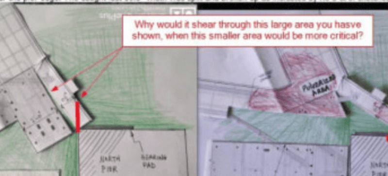
The purpose of my sketches was to show during the diaphragm sliding off the pylon the falling dead weight could help to tear off the rear 10.5" of Member 12 from the diaphragm's body.

In agreement with you it is entirely probable that NTSB reported blowout, to the north of Member 12, took place at the level of the 8" horizontal drain pipe, due to high concentration of stresses, and so above this drain pipe level there was no concrete left to be split from the rear 10.5" of Member 12. Nevertheless the splitting of the rear 10.5" of Member 12, commencing from the bottom upward, would be able to rip out the Member 12 north face vertical reinforcement cast in the first lift of the concrete pour.

 
RandomTaskkk (Structural)

2020-07-09_17-42_oljivt.png


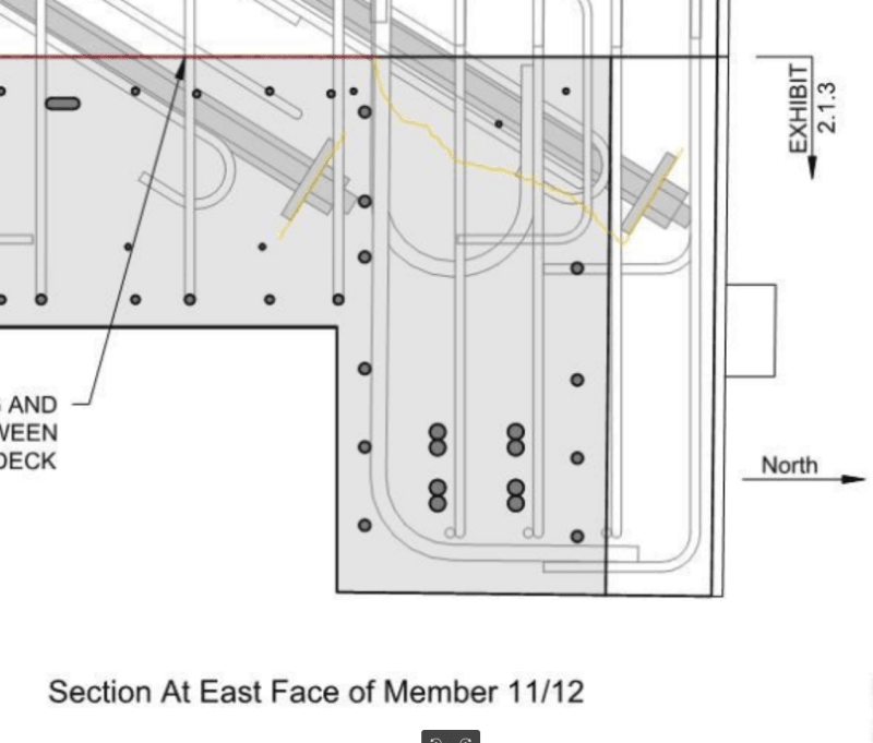
My guess is the shearing was probably trying the direction you were suggesting but the progress might have been impeded when the shearing crack hit 7S03 & 11S03 bars. Therefater the shear changed to splitting.
2020-07-09_17-48_v09e3d.png

2020-07-09_17-49_aowwwd.png


On the possible extra damage to the pylon and the rear of the diaphragm my explaination is as follow:-

On the pylon we have no information of damage. Secondly the bearing area of the pylon has been designed to take half of everything the bridge got so it will not shear off a corner if that is what you expected. Beneath the bearing there should be heavily reinforced with additional anti-burst reinforcement similar to the end of the post-tension anchor.

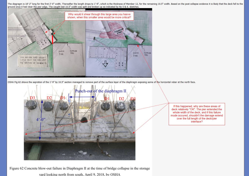
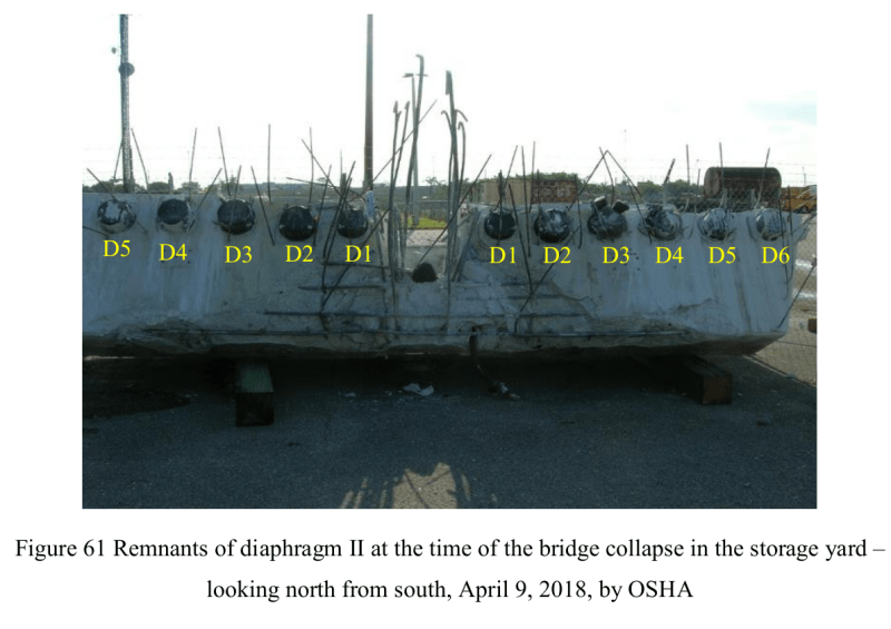
OSHA Fig 61 & 62 show a triangular layer section of the north face of diaphragm peeling off to expose the reinforcement inside. The reason only a limit section of the surface layer came off with Member 12 is due to the proximity effect. The splitting force came from the 1'-9" wide Member 12 and the OSHA 61 below shows the influence extending about 2 to 3 times the Member 12 width, about the bottom of anchor D3/D4, on either side at the bottom gradully reducing to 1 x width at the top. This is the same agrument like when considering the second moment of area of this bridge in resisting load one cannot take the full 31'-8" width of the deck but only a short section on either side of the web as the effective width for the bottom flange. Different codes allow different effective lengths but between 2 to 3 times the web width seems to be borne out by the evidence of this bridge.

The peeling off commenced from the bottom and would have travelled upward at an angle about 45 degree. It was abruptly stop near the tendon anchor D1 because the surface layer there was in high comression resisting the splitting.


F61_vissdz.png
 
Your "sketches" are just too good to leave alone. First - the legal disclaimers.
Background sketches courtesy of saikee119 (Structural) . No copyright violation intended.
DDDDave - this is the closest thing to tracing I can get. Sorry I can't meet your standards.
A decoder ring may be needed to correlate my numbering with that of Saikee - my numbers are one less than the numbering on his sequence of sketches.
3DDave - it is the author's intent that the background sketches are detailed enough to provide sufficient relevancy to the subject of this forum.

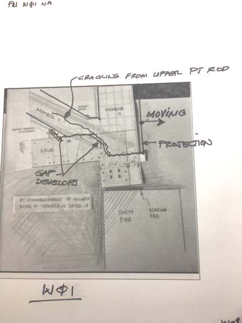
The next 5 sketches show what I think is the probable failure sequence. Please consider the sketches as sections cut thru the center of M11 and M12 so the internal voids can be illustrated.

W01 is basically depicting my idea of conditions while re-tensioning the PT rods in Member 11. The Node 11/12 had slipped about a half inch before retensioning began. The lower PT rod is anchored in the deck, the upper PT rod is anchored in the block which is moving with the bottom of M11 and M12 and which is being pushed out of the deck at the north end. The different anchorage conditions cause cracking in M11.
W01_note_add_t55qtj.jpg


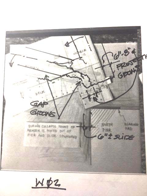
Sketch W02. The angle change in the deck, M11, and M12 is shown greater than I think is correct for a sliding distance of maybe 6 inches by the deck. At 6" slide I find the angle to be about 16 degrees. Internal voids increase and cracking increases as Node 11/12 pushes farther out the end of the deck.
W02_crack_added_mj1nzk.jpg


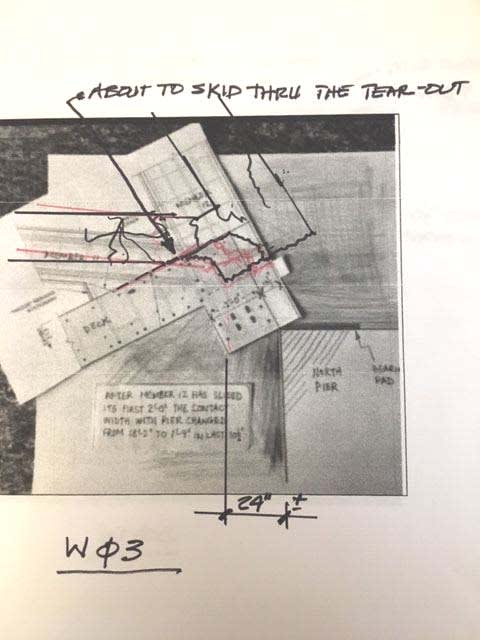
Sketch W03. Member 11 is just about to drop into the void left by the blowout of the block in the deck. Vertical load from M12 will likely break the end of M11, angles are changing quickly as Node 10/11 drops.
W03med_vgmf56.jpg


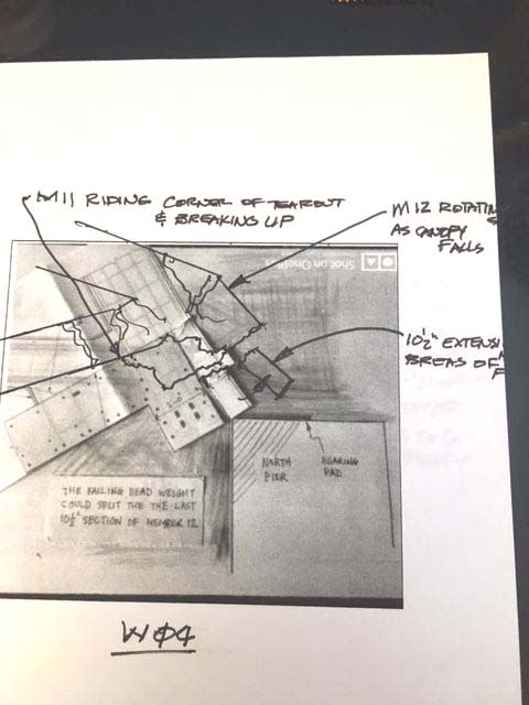
Sketch W04. Diaohragm just clears the edge of the pylon. The blow out block above the 8" pipe sleeve has cleared the end of the deck and is falling onto the top of the pylon. Member 11 is breaking up as it bends over the corner of the deck. The 10.5" projection of the deck under M12 and below the 8" sleeve is breaking off the deck.
W04xx_djdncp.jpg


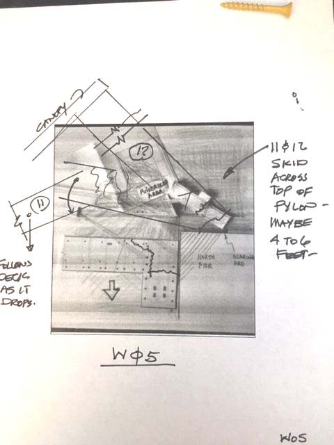
Sketch W05. The Deck is falling beside the pylon while the bridge pancakes and Member 11 folds against the deck. The lower ends of M12 and M11 skid across the top of the pylon and stay there. The canopy dives onto the deck as the deck hits the roadway.
W05xxx_owjmjm.jpg

OOPS! Pay no attention to that screw in the upper corner - that is not the screw you were looking for.

Th - Th - Th - Thats all, Folks!!
Thank you,
 
Sorry.
Totally wrong.
There are two triangles involved.
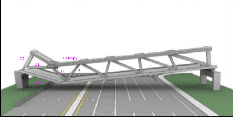
Triangle one is formed by member 11, member 12, and the canopy.
Triangle two is formed by member 11, member 10, and the deck.
When the collapse starts, the base of the second triangle starts to elongate.
Your sketch doesn't show this.
As the structure starts to fall, member 11 is pushed further out, hinging at the canopy.
Member 11 will continue to push out until the top of the canopy is at the level of the top of the foundation.
At that point, a little over 10% of member 11s length will be pushed out across the top of the foundation.
But don't forget the lower PT rod.
This is anchored in the deck.
As the collapse starts, the lower PT rod must break its way out of member 11.
There is no tension left on the rod but member 11 is moving north, as the structure falls the deck with the end of the PT rod is being pulled south.
In the first few inches the lower PT rod must break out of member 11.
As the structure falls the deck pivots at the lower end of member 10.
As the structure falls the deck is angled between the pivot point and the top of the foundation.
It doesn't take much fall of the structure for the deck to be pulled off of the foundation.
Member 11 is going north, the deck is going south.
image_dohcx4.png


This drawing is wrong.
The canopy and member 11 are shown too short.
At this stage of collapse geometry says that the 11,12 node will be pushed out past the north side of the foundation.
The deck is shown too long.
At this stage of collapse geometry says that it will have been pulled off of the foundation and be either sliding down the face of the foundation or have been pulled back enough to fall free.
I can do better than this but it will take a lot of time to first go back and find the bridge dimensions and then to set up the bridge as three pivoting triangles and show the relative positions as the structure falls.
It's grade ten geometry, but that doesn't mean that it won't take a lot of time.

Bill
--------------------
"Why not the best?"
Jimmy Carter
 
waross (Electrical) said:
that doesn't mean that it won't take a lot of time.
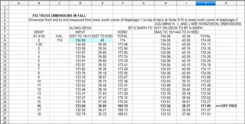
Not so long using a spread sheet. This is from about a week ago.
I used 134 feet from sta 0 to Node 9/10 but can change that in a sec.
Max O/O length of deck EDIT ADD measured from bottom of diaphragms and lower outside corners is at 4 ft drop of Node 9/10. That is the point where Node 9/10 passes thru a line between the lower corners of the diaphragms.
I assumed no crushing of concrete at Node 9/10 - the compression block is only about 2 inches deep.
FIU_HEEL_DIMENSIONS_AT_DROP_lpzkj0.jpg


Comments welcome.
 
Were you able to determine if the deck had began 'folding' at Node 9/10 before or after your observation of Member 11? Had Node 10/11 dropped at the time?
The canopy is shorter from top of M11 to top of M12 than the deck from bottom of M10 to bottom of M12.
Thanks,
 
There was discussion about a year ago about scan rates - could that affect the timing between the canopy (above) and the deck (below)? A top to bottom horizontal scan progression would seem to delay the imaging of the deck, giving it time to "catch up".
What affects frame rate in dash cams? Scan speed? Record/transmit speed?
Thanks,
 
To the best of my understanding, the frame rate is set so the dashcam doesn't fill up it's memory to quickly. The scan rate (top to bottom) would not be slower due to the frame rate. If the scan rate was slow, we would see bowing in the diagonals as they fell.

SF Charlie
Eng-Tips.com Forum Policies
 
Anyone care to venture how much time they have spent investigating this failure? The amount of time some of you have put in to this is incredible! There is so much that wasn't included in the NTSB report, at least not in-depth, that has been hashed out here and is great information. Not just as it relates to non-redundant CIP truss bridges (we aren't designing these anymore, right?) but from a mechanics standpoint as well!

Someday, when I have the time, I would like to read this thread in it's entirety. Thus far, I have only spent ~5 hours and most of that is just catching up on the past posts, while not fully comprehending the information that is in them or working through it in my head. My only request to the moderators is if there was a way to preserve all the embedded pictures within the posts for future learning, that would be great. In some of the old threads, the embedded pictures are unavailable, but maybe that has went away now?
 
Much talk here about Member 12 in this "truss". In a true truss, Member 12 is a zero force member. It was just intended to be part of the mast for the faux cable supports. Any benefit it had in trying to prevent sliding of Member 11 was likely just coincidence.
 
Right on.
So help me here - -
waross (Electrical)7 Jul 20 14:15
Gibbs Rule #39: There is No Such Thing as Coincidence.
Gibbs Rule #51: Sometimes You're Wrong.

Does Gibbs' Rule #51 apply to Gibbs' Rule #39?
(Love Gibbs Rules).
 
Personally I am not bothered by which hinges of 9/10/deck and 10/11/canopy moved first and consider it irrelevant. To me the hinge that matter is 9/10/deck and the canopy hinge is just to follow it.

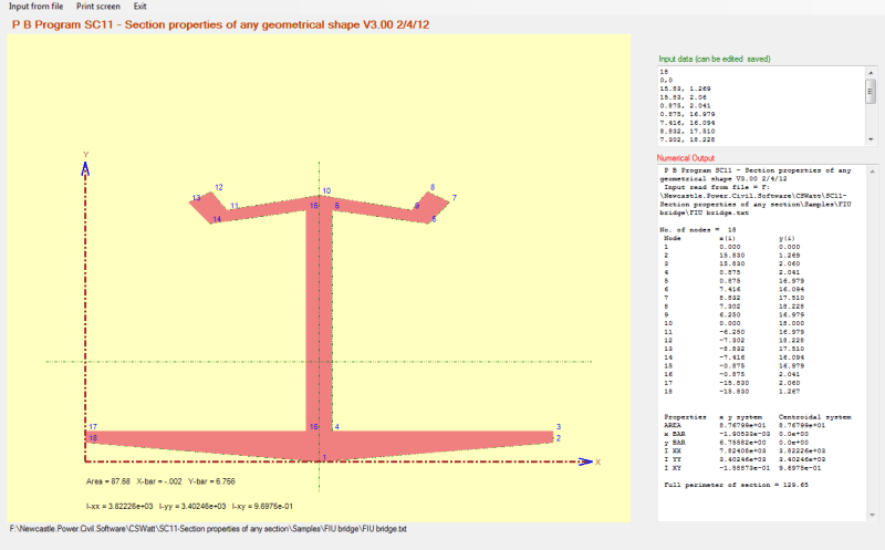
Full_cfihmw.png

Let's say before the collapse the full bridge has a second moment of area of 7824 ft4 and the centroid 6.756 ft from the bottom as computed by approximation using coordiate geometry.

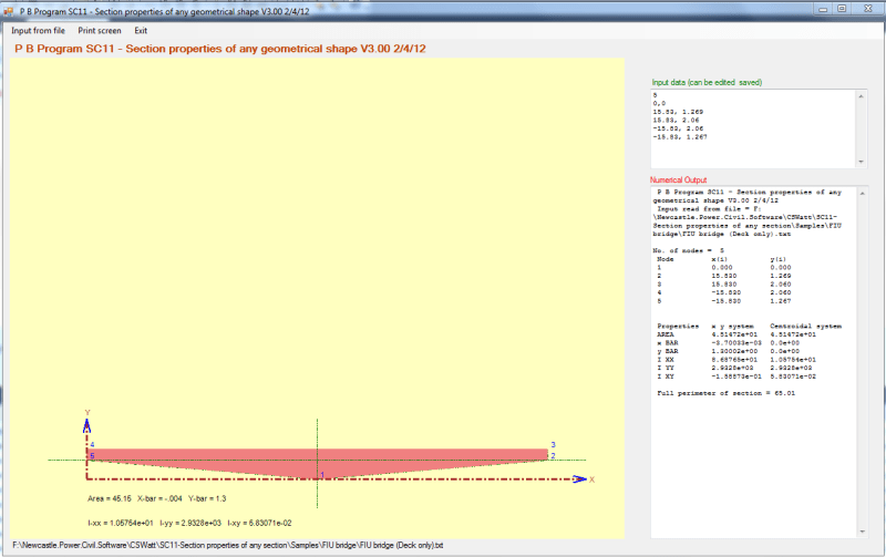
DEck_only_vlh3ac.png

One the 11/12 connection failed the web would be unable to hold member forces in the canopy in balance with those in the deck. The bridge was then supported by the deck only. The second moment of area and centroid would change to 18.69 ft4 and 1.3 ft respectively.

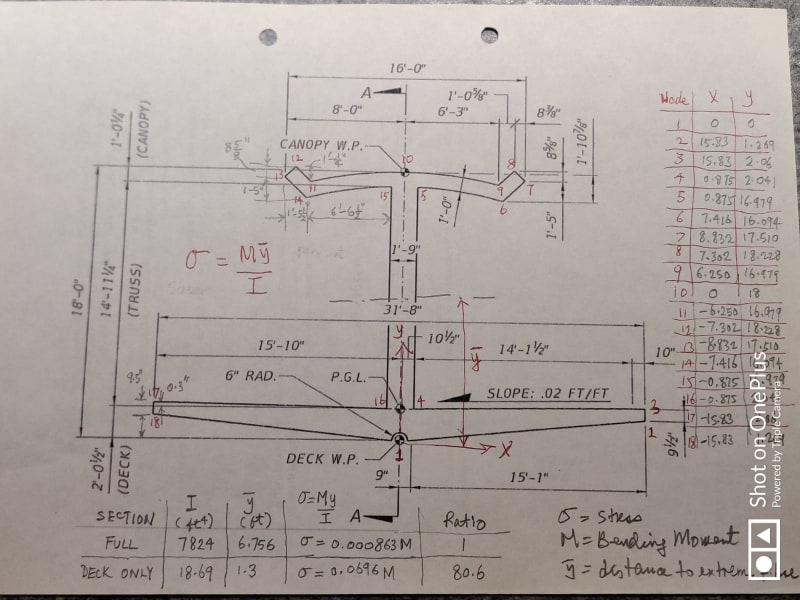
a67b9dc2-75c6-455e-bf15-8e55c58e384b_uigejw.jpg

From fundamental principle of stress = (Momentxdistance to extreme fibre)/(second moment of area) the stress in the deck-only case is about 80 times of the full deck. This huge stress increases is reslistic estimate if the postensioning was intended to cause the deck in full compression when the bridge is in ist final position

Therefore once the 11/12 connection has gone the deck would be hugely overstressed and formed a hinge at 9/10/deck. The hinge at 10/11/canopy was never a driver in the collapse.
 
BadgerPE (Structural)

We did spent a lot of time looking into what has happened.

Apart from formal education, on-site experience we can also learn from mistakes. Luckily for all of us the mistake is someone's else.

We have a wide range of disciplines in here and so far everyone is trying to accommodate each other's view and we all learn together.

There is an immense amount of record available. The project presentation is cunning. the design is unconventional. The construction sequence is extremely interesting. The photographic records are mind-boggling. The failure is intriguing and the manner of collapse is sublime to anyone who wish to learn. If that isn't enough the FOT reviewing engineer was able to mark up the drawings the failure risks of this bridge years before they happened.

OSHA, WJE, NTSB and FIGG reports were each prepared to serve a certain purpose and they were constrained by the insurance people. What we are doing here is for the academic interest of getting really into the very bottom.

As far as I know this forum had discovered the root cause long before any of the official reports came out.
 
Status
Not open for further replies.

Part and Inventory Search

Sponsor

Back
Top