Eng-Tips is the largest engineering community on the Internet

Intelligent Work Forums for Engineering Professionals

  • Congratulations waross on being selected by the Eng-Tips community for having the most helpful posts in the forums last week. Way to Go!

Miami Pedestrian Bridge, Part XIV 78

Status
Not open for further replies.

JAE

Structural
Jun 27, 2000
15,433
US
A continuation of our discussion of this failure. Best to read the other threads first to avoid rehashing things already discussed.

Part I
thread815-436595

Part II
thread815-436699

Part III
thread815-436802

Part IV
thread815-436924

Part V
thread815-437029

Part VI
thread815-438451

Part VII
thread815-438966

Part VIII
thread815-440072

Part IX
thread815-451175

Part X
thread815-454618

Part XI
thread815-454998

Part XII
thread815-455746

Part XIII
thread815-457935


Replies continue below

Recommended for you

saikee119 said:
If that isn't enough the FOT reviewing engineer was able to mark up the drawings the failure risks of this bridge years before they happened.

Could you point me to this information please? Sounds quite interesting!

Your post as a whole was spot on! Failures are unfortunately a great learning opportunity. Especially when they are on the edge or beyond what is considered “normal” design. As I said before, I haven’t spent as much time on this one, not for lack of interest, but more to time and the unlikelihood that I will ever design a bridge. The Hard Rock, Salesforce Transit Center, Millennium Tower, and Opal Tower issues are all more relevant to my day to day so I’ve spent significantly more time there.

 
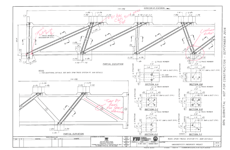
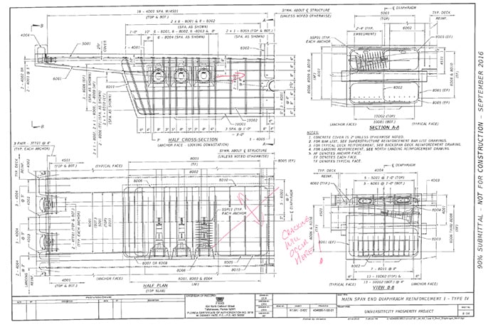
The FDOT markup was of localized cracking potential - there was no numerical evaluation of the eventual underlying structural failure. Every sharp transition in concrete will localize deformation into small nuisance cracks. It does not appear he had any safety concerns. I forget what the specific recommendations were but I believe the response was adding some fillets. There are markups. See document page 61, pdf page 80 of NTSB report HAR1902. From that report:

According to FDOT, the review performed on this project by the FDOT SDO—

was consistent with reviews performed on all projects; it consisted of a high-level
review only. We did not perform calculations or review EOR calculations
 
Hi Vance.
Getting close.
A big part of the time will be to find the post with the dimensions of the bridge on a slow internet connection.
What I would look for is:
Distance between the piers.
Overall length of the deck.
Horizontal setback of the point at which the canopy hinges from the end of the deck.
The length of member 11 from the canopy "hinge" to the extreme north end.
Assuming that the deck and canopy hinge is centered on the PT bars, the height of the canopy PT bars above the deck PT bars (center to center).
I have read speculation that the rebars across the plane of failure were fully embedded in the concrete.
I have read speculation that the proximity of the 4" sleeves severely compromised the ability of the concrete to maintain a bond to the rebars.
(Was that the same poster?)
The 1/2 inch crack should have been measured horizontally.
That was the direction of displacement.
Say about 3/4 Inches.
Despite speculation to the contrary, once the 11/12 node had moved 3/4" horizontally, the rebar was now loose in fractured concrete.
The lower PT rod was all that was left holding it together.
At this point I speculate that the PT rod was crushing the corrugations in the sleeve.
High school physics: Flotation: The PT rods were rigid at the time of the concrete pour. Buoyancy in the wet concrete would have lifted the sleeves against the bottom of the PT rods.
Now, as the tension on the lower PT rod was increased, the PT rod commenced to crush its way out of member 11 in a horizontal direction.
What else?
The 11/12 node was moving north and the deck was moving south.
The PT rod was crossing the plane of separation and had to be crushing the bottom of member 11 horizontally.
As the movement continued, the top end of the PT bars would be extending out of the top of the blister.
This horizontal crushing continued until the deck cleared the foundation and started to fall.
At that point the the PT bars would be again pulled into the top of member 11
Once the slack in the PT bars was taken up, the horizontal crushing became a mostly vertical ripping.
There has been speculation that the PT sleeves were 4" in diameter.
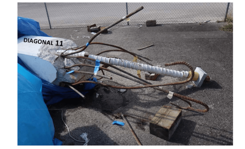
There are some pictures of the rods and the sleeves prior to the concrete pour.
The sleeves appear to be about 150% of the PT diameter or 2.5" to 2.625".
This is moot however because buoyancy will have lifted the sleeves up into contact with the bottom of the PT rods.
The other thing that will take time is doing some auto-cad drawings of the various components as the structure fell.
My cad skills were never very good and I don't use it many times in a decade.


Bill
--------------------
"Why not the best?"
Jimmy Carter
 
BadgerPE (Structural) said:
Quote (saikee119)
If that isn't enough the FDOT reviewing engineer was able to mark up the drawings the failure risks of this bridge years before they happened.

Could you point me to this information please? Sounds quite interesting!

The Interactive: The Path to the FIU Bridge disaster set up be NBC has recorded some basic information by FDOT Engineer Thomas Andres.

I believe FIU also have some records. There were some marked up drawings originally but later converted to typed text and replaced by computer CAD sketches.

Here are just two of the original mark-up drawings by FDOT engineer.
9-15-16_Andres_Note_on_Member_11_lak20b.png

Andres_said_cracking_will_occur_here_k2wjaq.jpg


FDOT engineer was doing a high level review. The cracks were marked on areas whererever uneven stress areas were apparent. They were based on years of experience on postensioned concrete. As the bridge wasn't owned by FDOT so the peer review was given to a appointed party. Nevertheless FDOT offered a brief overview which proved highly relevant.
 
That is a laundry list.
A set of drawings in PDF here:
Dimensions are on Drawing B37.
The changing dimensions during fall are not real sensitive to exact location of Node 9/10.
If you check the spreadsheet the "top of deck" dimensions are measured along the deck surface.

At this point I am hesitant to advance an opinion as to just where the canopy hinged. At the north end of the blister? Intersection of PT rods? Hard to tell. Easy to change in spreadsheet. By the way, to check my spreadsheet, do the math on one drop point. The same formulas are used to find the output in each column.

Flotation - a 3" sleeve displaces 7.3 pounds of concrete per foot. A 1.75" steel rod weighs 9.17 pounds per foot.
This horizontal crushing of Member 11 ? continued until the deck cleared the foundation
It is my thought that at some point the remains of Node 11/12 have departed the deck and are simply being pushed wherever, and that may have happened before the deck fell off the pylon. I attempted to convey that idea in my sketch W04. When Node 11/12 clears the deck and has no connection to the deck depends mostly on dimensions and damage.
For the most part, we are tracking together pretty well.
Thanks,
 
This may be crazy but could the bolt end of the PT cable have had too little concrete for compressive force and crushed the bearing concrete?
 
ChiefInspectorJ said:
could the bolt end of the PT cable have had too little concrete for compressive force
That is not crazy and thankfully not often the case.
It is not crazy because it is a concern and is in most cases the responsibility of the PT contractor. The PT is usually considered a design/construct sub who is responsible for doing it right. The contractor in this case has an excellent reputation. I have worked with their southern CA people.
The compressive stress under the anchor plate is quite high - as I recall something like 70% of specified concrete strength. To compare, working stresses (real) under the previous codes limited bending compression to 45% of specified concrete strength.
We would need access to shop drawings submitted for the PT to check the stresses.

 
ChiefInspectorJ (Specifier/Regulator) said:
This may be crazy but could the bolt end of the PT cable have had too little concrete for compressive force and crushed the bearing concrete?

We should discount the fear of the PT rod overcompressing the concrete.

2020-07-11_13-31_ddlxir.png

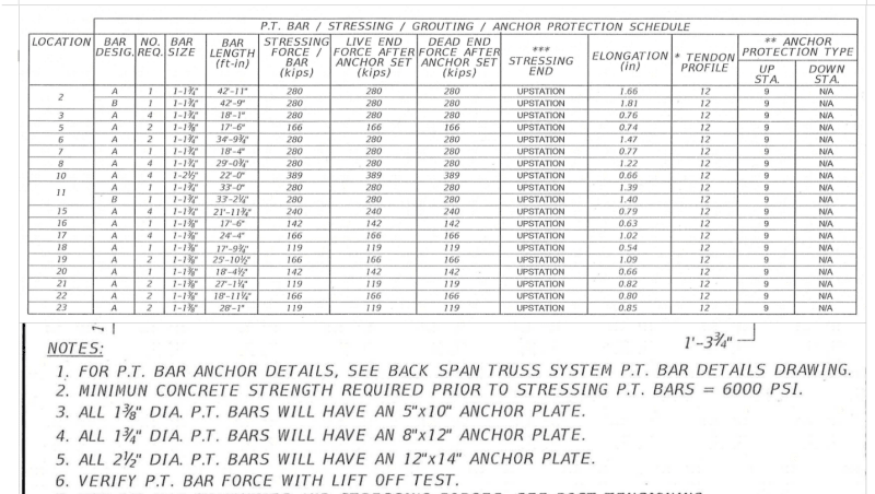
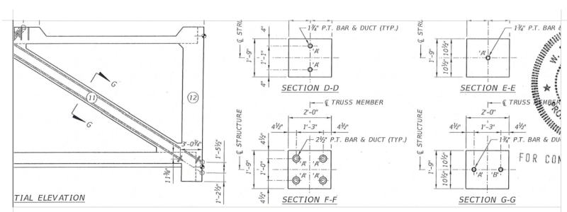
We know from the contract drawing the PT rod inside member 11 is 1.75" diameter, PT rod tension is 280kips, anchor plate size 12"x8" and the specified concrete strength is 6000psi.

member_11_cross_section_adekor.png

The cross section of Member 11 is 24"x21".

If the entire 280kips bears on the concrete immediately behind the 12"x8" anchor plate the compressive stress is 2917psi. If the two 280kips PT rod tensions bear on the full cross section of Member 11 the average compressive strength is only 1111 psi.

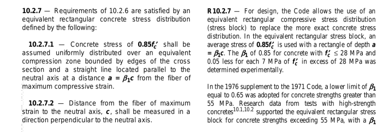
ACI_318_on_concrete_stress_lfe93y.png

ACI design codes, say 318, permits only 0.85x specified strength to be used in design in conjunction with other considerations. Thus below a stress of approximately 0.85x6000 = 5100 psi is a safe design.

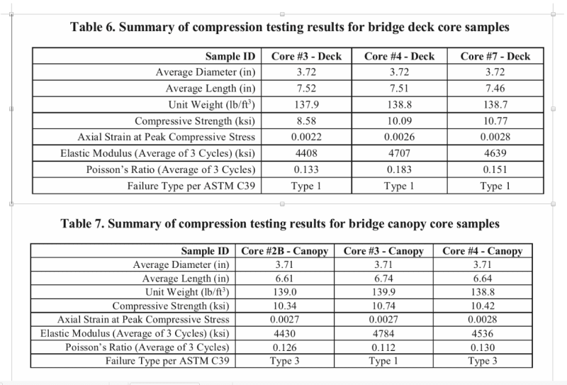
If the concrete is about to fail the actual concrete compressive stress is of course allowed to reach to the specified strength but there is fat in the system that the actual strength is invariably higher than the specified strength. When NTSB cut cores from the collapsed bridge to test the concrete strength in a laboratory the lowest actual strength was 8,580psi while the remaining four samples registered strength all above 10,000psi.
Core_strength_jr4mc8.png


Thus I don't think there is much mileage in proving the concrete could be overstressed by the PT rods in compression. To me the concrete in trouble is in the area outside the influence of the PT rods with not enough compression.
 

That solves that. Thank you for your detailed post and data coverage.
I do see one thing on which I will comment - as I recall viewing photos of the PT rod anchor plates which had anchored the PT in Member 11 they appear square to me - not rectangular.
EDIT ADD: I think we should look for a specific allowable compressive stress under an anchor plate at the time of tensioning. The general usage of O.85f'c is for factored loads. Under PT installation the load is real and temporary until it relaxes or anchors set, and some increase is permitted but I am not sure it reaches 0.85f'c.
Had a reference but just lost power for a few minutes so will return in a bit. Hopefully with a reference.
Thanks,
 
Vance Wiley's (Structural) said:
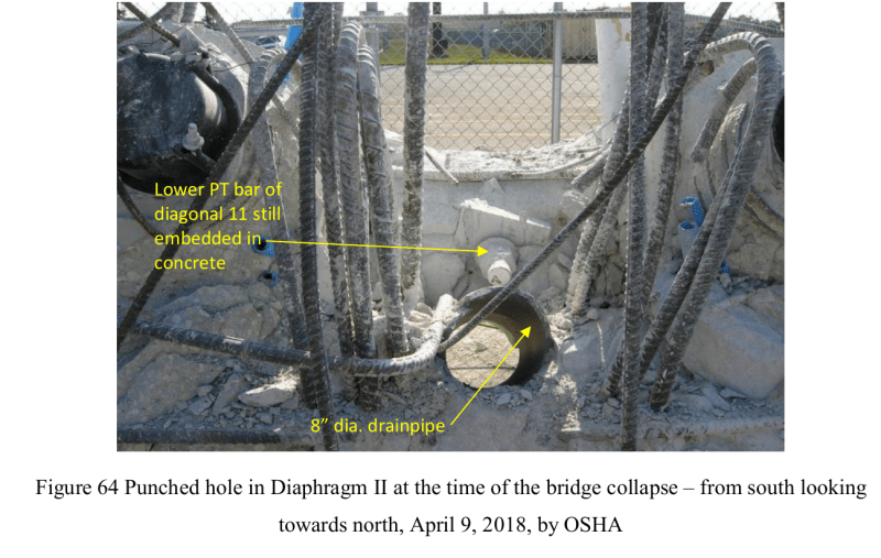
I do see one thing on which I will comment - as I recall viewing photos of the PT rod anchor plates which had anchored the PT in Member 11 they appear square to me - not rectangular.

F64_ak9jwp.png

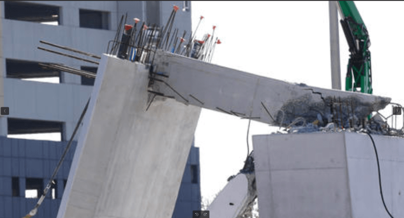
Many photos, like OSHA Fig 64, 65 & 67, show the PT rod anchor enembedded exposing only one ful edge. Hence measuring the two sides is not possible and I agree it does appear to be square in shape. I attached OSHA Fig 64 for example.

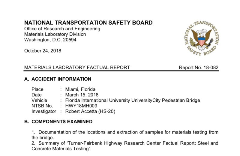
NTSB_report_heading_egulpb.png

The best photo I could come up with for checking the PT rod anchor is from NTSB "Materials Laboratory Factual Report (Report No. 18-082) depicted above.

Fig_15_1_Member_11_nsux4r.png

In its lower section of Fig 15 enclosed above you can save the image, magnify it and measure the horizontal and vertical edge. When I did that I got a aspect ratio of 1.5 so the anchor is definitely rectangular to me. The specified dimension of it is 12" by 8" for 1.75" diameter PT rod used in Member 11.
 
Vance Wiley (Structural)

In my experience the 0.85f'c used in ACI code is to encompass a safety factor for the concrete as a material. When you do ultimate limit state design the ultimate tensile strain is 0.003 at collpase. You also have a strength reduction factor 0.9 making the net usable strength in concrete 0.9x0.85 = 0.765f'c for a ACI compliant design.

The Euro code ultimate tensile strain in concrete is 0.0035. The ultimate maximum concrete stress is equal to the specified concrete cube strength fcu divided by the material safety factor which is 1.5 for concrete. So the corresponding net usable ultimate concrete stress is 0.6fcu.

However concrete strength crushed by a cube is higher than that crushed by a cylinder. The universal conversion factor is f'c = 0.8fcu. Therefore EURO or Bristish designer would effectively use 0.6/0.8 = 0.75f'c which is close to the ACI code's 0.765f'c.

What you permitted in the design, by lowering f'c to 0.85f'c and then further reduced with a strength reduction factor, is just good engineering practice adopted universally but in slightly different formulae for different countries.

In the field the specified 6,000psi strength concrete actually has the insitu strength at least 8.580psi verified by the core samples. The acutal collapse analysis should based on the actual strength and actual stress.
 
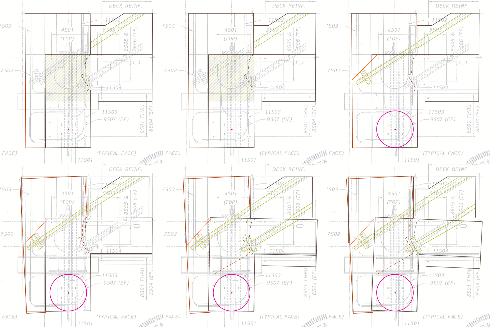
The collapse in five frames:

saikee's surface is indicated in chevrons and as I've explained before, I give it zero strength to hold 12 in the slab socket.

12 bows north under load from the horizontal component of 11, held in place at the top by the canopy and at the bottom by the diaphragm. The slab carries the downward component of 11 and passes the load around 12 to the diaphragm. Interestingly, when I rotated the upper PT rod to follow 12, I noticed that it would have to increase in length. This can't happen unless, say, the tension is released in the rod, a plausible explanation for the "cracked all to ..." upon detensioning.

I speculated earlier that the lower PT rod was a snag that prevented the structure from fully collapsing however, upon closer inspection of the PT rod duct spec and allowing for the 32 degree inclination, that allows over two inches of freedom for the horizontal movement. I now tend to believe that the structure held together with the few rebar threaded through 12 and the slab, as well as the rebar in the nodal block.

The strain from the retensioning eventually overcame the last vestige of connectivity allowing enough extra horizontal movement to cripple 11 which likely failed just above the nodal block (given all of the visible damage before the retensioning). As 11 pancaked and hammered into the nodal area, the primary rotation came from the slab which started its downward descent. Interestingly, the lower bound of the vacated socket area becomes a tension break. I believe until this time, 12 was able to absorb the strain.

Edit: Eventually 12 skips off the north end but that part is rather anticlimactic. Edit 2: I redrew the PT rod anchor plates to 8" in profile and relocated that lower PT rod closer to its as built condition. The orange line represents what I believe is the 45 degree bending shear plane in 12. It appears early in the gif but I got tired of editing.

Ultimate_Failure_of_Member_12.02.0.0_degree.05_k9zg3j.gif
 
Thank you Sym P. le
Your animation starts to illustrate the point that I have been trying to make.
There are some adjustments that you may consider.
Your animation shows the lower PT rod kinking. There is no photographic evidence of a kink.
It would instead have been breaking out of the lower part of member 11 in the area to the right of where the kink is shown.
You show the 11/12 node pivoting at the bottom. On reconsideration, you may agree that the pivot point was the canopy above member 10.
The 11/12 node would be rotating CW, not CCW and there would be separation between the deck and the 11/12 node.
The animation shows rotation. In fact there would have been little rotation initially but there would have been horizontal separation.


Bill
--------------------
"Why not the best?"
Jimmy Carter
 
Sym P. le (Mechanical),

You presentation with the changing static images is novel so is your postulation. The idea that Member 12 was pushed out, hinged somehow at the bottom and split at the deck level with Member 11 sounds exquisite and not without merit. The holding down bolt on either side of Member 12 could have provided the rotation point have indicated with the pink circle.

However there are some weakness in the postulaion of which among them are:-

(a) The separation of Member 11 from 12 at deck level, as confirmed by you couldn’t happen unless the tension of the PT rod is released. Therefore the photos available on 15 Mar, prior to re-tensioning, should show signs of the separation. FIGG has submitted seven photos dated 15 Mar to NTSB and I enclosed two of them here. The bridge was re-stressed from midday of 15 Mar and then collapsed.

west-1_s3itpm.png

The is no sign of any crack showing a separation of Member 11 from 12 on the west face.

East-1_k9bkyh.png

On the east face a small crack is visible but it seems to trace back to the PT rods which have caused rather alarming surface cracking on both east and west faces of Member 11.

(b) If there has been a separation crack of Member 11 from 12 at the deck level then we can expect the Member 12 joint with the canopy to be pushed outwards and suffered some permanent damages. The actual joint, between the canopy and Member 12, appears remarkably intact after the collapse and remains substantially at 90 degree when I measured it for any permanent deformation.
Canopy-12_lzp2qw.png


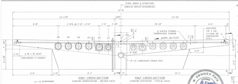
(c) The ability of Member 12, which is only 1’-9” thick, could cause a rigid body rotation of the 18’ long diaphragm is stretching the imagination a bit, bearing in mind in the postulation Member 12 would have already partially separated from the deck and Member 11. I attach the end elevation of the diaphragm to show its relative size to the Member 12.
diaphragm_pzixan.png


(d) If the evidence in the field is inadequate to support your postulation after the 11/12 has been de-stressed and the bridge was resting between piers then the subsequent re-stressing would make any separation crack between Member 12 with 11 even more difficult to occur because the upper PT rod would instantly clamp the two together. It was stated in NTSB report that the upper PT rod was first fully re-stressed, the 280 kips re-stress of the lower PT rod was just completed and the bridge fell.

I think the actual failure mechanism could remain a mystery for some time to come.
 
We have two triangles.
Triangle #1. Member 11, member 12 and the canopy.
Triangle #2. The deck, member 11 and member 10.
Triangle #1 pivots at the member 11/canopy joint and slides across the foundation to the north.
Triangle #2 pivts mainly on the foundation but triangle #2 is distorting. The base is elongating and is the sum of the last section of the deck and the gap created as the 11/12 node moves north. This continues until the base falls free of the foundation.
The length of member 11 is approximately 30 feet.
The horizontal component component of member 11 is approximately 26 feet.
As the bridge falls the 11/12node will move approximately 4 feet north until member 11 is close to horizontal.
To do so, the lower PT rod must be breaking its way out of the bottom of member 11.
By the way, the lower PT rod is anchored in the deck which moves very little.
The lower PT rod will be extending out of the top blister until the deck falls free.
Once the deck falls free, the slack in the lower PT rod will be taken up and then continue to break out of the bottom of member 11.

Bill
--------------------
"Why not the best?"
Jimmy Carter
 
Why was member 11 destroyed?
Member 11 pushed the 11/12 node about 4 feet north.
When the bottom of member 12 cleared the foundation, it would have dropped until the bottom of member 11 contacted the foundation.
At this point member 11 would have been already severely damaged by the lower PT rod.
I can't find an exact dimension for the height of the deck above the foundation. I estimate from 2 to 3 feet.
That drop would be enough to finish the damage to member 11.

The lower PT rod as a pin.
Much has been made of the clearance between the sleeve and the PT rod.
The position has been taken that there was too much clearance for the PT rod to act as a pin.
Back to high school science.
Buoyancy.
The bigger you estimate the diameter of the sleeve, the more buoyancy it will have in the wet concrete to float up against the bottom of the PT rod.
It is possible that as the joint started to fail the first 1/2 inch or so, the PT rod had enough clearance in the sleeve to both crush a little of the concrete and to curve upwards in the sleeve.
That 1/2 inch gap would have relieved the tension on the PT rod.
When the rod was retensioned, that would create a force on the top of member 11 to push it northward and may have added a further crushing force to the concrete as the tension tended to straighten any curve in the rod.

Bill
--------------------
"Why not the best?"
Jimmy Carter
 
waross (Electrical) said:
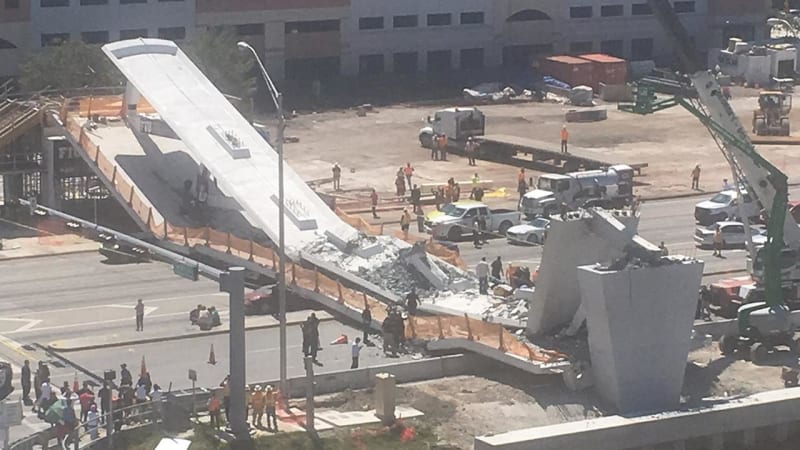
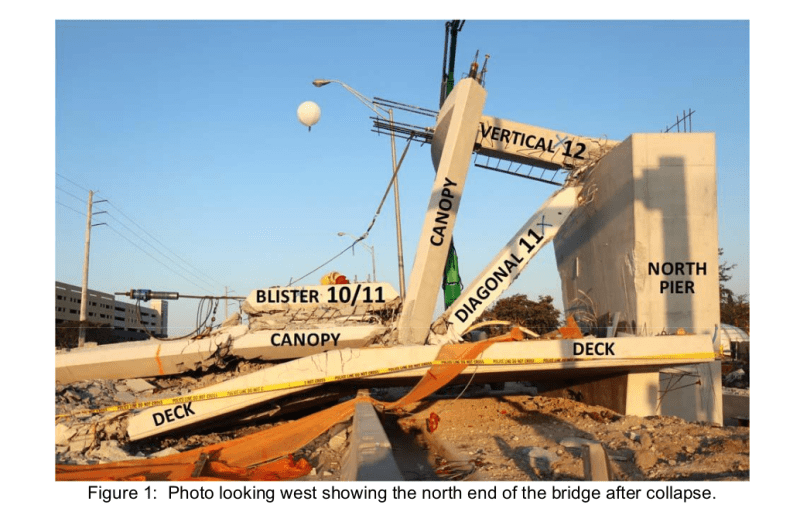
I can't find an exact dimension for the height of the deck above the foundation. I estimate from 2 to 3 feet.

3221155_1280x720_jm0bhw.jpg
Fig_1_nkykzq.png

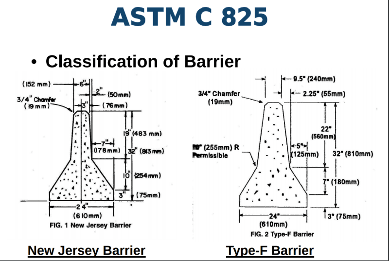
The above show that the diaphragm dropped to the ground while the other end was resting on precast concrete barriers.

Barrier_ymnubr.png

Barrier to ASTM C825 seems to have 32" height so your height estimate is spot on.

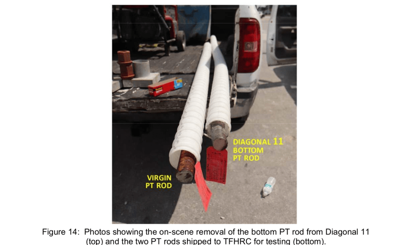
Fig_14_2_PT_rod_sleeve_about_1.5_of_rod_c4fiiu.png

NTSB material laboratory factual report lower section of Fig 14 shows the end of PT rod with a sleeve. My measurement is the internal diameter of the sleeve is under 3" making its overall diameter, including the ribs, about 3". You can download the image, enlarge it and scale it yourself.
 
As I recall, Diaphragm 2 is 4'-0 1/2" in height at the center of the bridge. I have not seen how thick the shim plates were.
So top of 8" pipe sleeve was a little more than 2 feet above the top of the pylon.
 
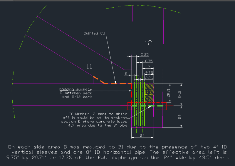
Here is a dimension:
image_goh7yo.png

When the 11/12 node went off the back of the pier it would have dropped 48.5 inches until the bottom of member 11 contacted the top of the pier.
Note, the 11/12 node went off the back of the pier, not the front as has been suggested in several drawings.
It would have moved about 4 feet north and the lower PT rod would have broken away 4 feet of the bottom of member 11.
Following that, the continued fall of the structure would have pulled the 11/12 node back across the top of the pier, explaining the damage to the bottom of member 12.

Bill
--------------------
"Why not the best?"
Jimmy Carter
 
Status
Not open for further replies.

Part and Inventory Search

Sponsor

Back
Top