Eng-Tips is the largest engineering community on the Internet

Intelligent Work Forums for Engineering Professionals

  • Congratulations waross on being selected by the Eng-Tips community for having the most helpful posts in the forums last week. Way to Go!

Miami Pedestrian Bridge, Part XIV 78

Status
Not open for further replies.

JAE

Structural
Jun 27, 2000
15,433
US
A continuation of our discussion of this failure. Best to read the other threads first to avoid rehashing things already discussed.

Part I
thread815-436595

Part II
thread815-436699

Part III
thread815-436802

Part IV
thread815-436924

Part V
thread815-437029

Part VI
thread815-438451

Part VII
thread815-438966

Part VIII
thread815-440072

Part IX
thread815-451175

Part X
thread815-454618

Part XI
thread815-454998

Part XII
thread815-455746

Part XIII
thread815-457935


Replies continue below

Recommended for you

A correction to my previous post.
The foundation or pier is 6 feet wide, not 4 feet wide.
Although the 11/12 node was pushed northward over 4 feet, it did not drop off the back side of the pier.
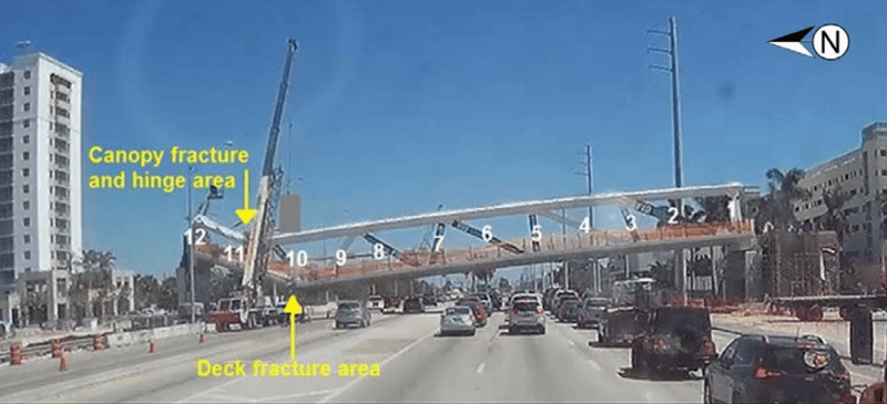
This picture is taken at the moment that member 11 is substantially horizontal and the 11/12 node is at its farthest travel northward.
image_lkkfip.png

At the time that this was taken the deck has fallen about the height of the canopy.
As a result, the distance between the south end of the deck and the north end of the deck is less than the sum of the two portions of the now broken deck.
This will increase the separation of the plane of fracture.
The lower PT rod is anchored in the deck and the 11/12 node has now moved over 4 feet 9 inches north of the end of the deck.
At the moment that this picture was taken the lower PT rod has already crushed its way out of about 5 feet of the bottom of member 11.
Members 11, 12 and the canopy will have continued to rotate until member 11 contacted the top south corner of the north pier.
The damage to members 11 and 12
is consistent with that contact.


Bill
--------------------
"Why not the best?"
Jimmy Carter
 
The peer reviewer Louis Berger negotiated with FIGG for $61,000 to undertake the cheek the adequacy of the bridge only in the finished condition.

Thus in Louis Berger review the 11/12 would be bolted tight with the short span which can conveniently used as a restraint to stop 11/12 any idea of moving to the north. If 11/12 has serious cracks previously FIGG/MCM has to made good to it and the bridge would not failed afterwards.

However the bridge without the short span is also a valid load condition and so without its inclusion the certification of the bridge adequacy is not complete.

Therefore the peer review contract between FIGG and Louis Berger although legal, does not materially deliver a true verdict on the adequacy of the FIU bridge in substance.
 
The PT rod as a pin.
This suggestion has been dismissed.
I suggest that this is a reaction to not considering this possibility in the first place.
Assumptions have been made to dismiss this suggestion.
On the other hand is evidence and probability.
Consider the sequence of the failure of the construction joint:
Such a failure is most often progressive.
The first displacement weakens the joint and leads to further failure.
When the failure does not progress the two most common reasons are that the displacement caused by the failure has lessened the forces across the plane of failure or some other factor or object has acted as a mechanical blockage.
The first cracking did not compromise the rebar but did lessen the force of the PT rod, hence the failure stopped with visible cracking when the PT force was relieved. At this point the rebar was holding the joint. together.
The second displacement of the plane of failure was 1/2 to 3/4 inches. Why did this stop separating?
The geometry was such that the force due to the weight of the structure was not decreasing.
The tension of the PT rod was removed with the first fraction of an inch of displacement.
If the rebar was unable to prevent the displacement it is unlikely that the rebar would be able to stop the movement abruptly.
If the rebar was full length it may have had a restraining effect but this was a lap joint.
A rule of thumb is that a rebar embedded to 40 times its diameter will break before being pulled out.
The rebar did not break.
The most reasonable explanation is that the loose pin formed by the lower PT bar became tight and stopped the movement.
When the rebar was retensioned, the pin failed by way of the destruction of the lower part of member 11.
Do not discount the buoyancy of the sleeves. The larger that you assume the sleeves to discount my suggestion, the more buoyancy they will have to support my suggestion.
Then gravity.

Bill
--------------------
"Why not the best?"
Jimmy Carter
 
Nor did the peer review process seemingly comply with that required by the FDOT which included all stages of construction and in this case transportation.

Apparently it also didn't include analysis of the "nodes" or joints, only the main structural elements ( deck, canopy and struts ).

Unbelievable.

Remember - More details = better answers
Also: If you get a response it's polite to respond to it.
 
The review was a failure because it didn't properly analyze the strengths of the nodes in the truss. It had nothing to do with not analyzing the bridge during construction stages. Now, if the analysis had found that the nodes were only strong enough when the bridge was completed then that was a failure to realize that the main span could NOT rely on the back span to strengthen or support it.
 
LittleInch (Petroleum) & LionelHutz (Electrical)

In a real world you can always try to engage somebody to do a peer review of a Rolls Royce standard by a watertight specification. For just $61,000 the offer would still be a Toyota Yaris and the offer would be written in into the contract the exact scope of work and every deliverable.

To do a reasonable peer review you need a PE, attendance to formal meeting half a dozen times, months of work by a couple of junior engineers to do number crunching, modelling and calculations, report writing and expenses to go with the job. That is just one iteration assuming no change is needed in the design.

Every drawing for construction in this project, which forms the input to any peer review, has four signatures of
(1) Prepared by - possible by a technician/draftsman/CAD operator
(2) checked by - detail check against calculation by a junior/assistant engineer not yet qualified.
(3) Designed by - checked by the designer himself to ensure his idea correctly implemented
(4) Approved by - signed by senior PE who owns the project, selected the scheme and created the initial general arrangement.

Had the design been properly executed the in-house peer review should have picked up any anomaly too.
 
The PT rod as a pin thing I think is a little bit simplistic. There was a bunch of stuff going on as soon as the joint started to move. The weedy looking cage of rebar at the base of member 11 holding it to the deck which was in shear from the moment they took the supports away probably bent a bit or maybe sheared the odd one. Then a host of other restraints came into play like all those vertical bars in member 12 you see on the OSHA photos, other bits of re-bar and possibly the PT rods. But it wasn't the only thing stopping it sliding away as soon as member 11 took its full dead load.

The whole tensioning / de tensioning of member 11 was an after thought and when they laid the end on the pier and took the transport away, the compressive load was very high from dead load plus the tensioned member 11. Sure it only apparently lasted an few hours before they de tensioned the rods, but that was still a high load going into inadequate re-inforcement.

Then of course re-tensioning it ( mainly the lower bar) was almost certainly what broke the thing as the additional load forced member 11 off the deck along the crack / failure plane. Once one or two bars snapped or lost their ability to hold member 11 then the rest went in a cascade.

Any sort of overview of the design only looking at the final layout wouldn't pick up any issues with that node because it would seem clear that any forces would be balanced by opposite ones from the second span.

Remember - More details = better answers
Also: If you get a response it's polite to respond to it.
 
saikee119 - why are you telling me how a peer review should have worked?


Any sort of overview of the design only looking at the final layout wouldn't pick up any issues with that node because it would seem clear that any forces would be balanced by opposite ones from the second span.


I haven't seen anything about the design yet that would support the back span being capable of properly supporting that node. Would you butt something against the end of a steel truss to stop the welds on a diagonal from ripping off the bottom stringer?
 
I think you meant to say "off the back of the DECK" here.
The base of M11 and M12 may not have fallen 4 feet - at least in an abrupt manner. There is considerable material missing from the end of the deck which was initially directly below M11 and M12 - principally in the zone between the top of the deck surface and to the top of the 8" pipe sleeve, which basically defined the bottom of the "blow out block".
This would not ivalidate your interpretation of the failure but only lessen the drop at that step where M11 and M12 were no longer atop the deck.

 
In this case, probably unlike the welded heel joint to a steel stringer, the "back span" was to be cast against the north end of the deck and M12 of the main span. Then the two spans were to be "clamped" together with 1100 kips of post tensioning.
This is Canopy PT C1 and C4 noted to be "MAIN SPAN BACK SPAN CANOPY and 270+ feet long on drawing B-69.
I would have achieved that part differently but there are more ways than one to skin a cat. The cat does not appreciate any of them.
 
This thread is just going in big circles. The ability of the rest of the structure to stop that node from coming apart vs the expectation of the rest of the structure performing that task vs the practicality of the rest of the structure performing that task was already discussed in detail.

I don't believe it was designed to work that way, should have been expected to work that way or would have properly worked that way. I believe the comments about the rest of the structure stopping the node from coming apart once it was built would have led to yet another blunder in the design and construction if the structure had survived long enough to get that far.
 
Thank you Vance.
Actually I did mean to say that but I was in error and posted a retraction.
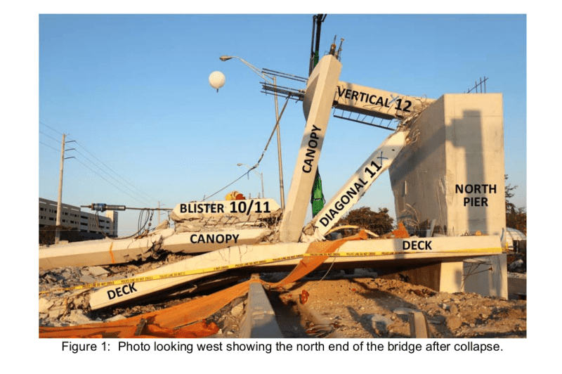
The total displacement of the 11/12 node was about 4'9". The top of the pier was about 6 feet.
The 11/12 node never left the top of the pier.
The damage to the 11/12node was most likely done when member 11 contacted the top south corner of the pier as everything continued falling.

I can't accept the repeated sketches of the 11/12 node rotating off of the south side of the pier.
In the initial collapse that node was moving north, not south.
If the 11/12 node was damaged then by what act of God was member 12 lifted up into its final position on top of the pier.

Thank you for your comments LittleInch.
I suggest that the postulations that ignore the movement to the north of the 11/12 node, and which ignore the PT bar completely are more simplistic.
I don't suggest that the PT bar prevented movement.
I suggest that as the rebars were progressively failing, The PT bar arrested further movement after the original crack of 1/2" to 3/4".

How could member 11 move north in relation to the deck without the Pt bar ripping out.
image_bhstca.png


Bill
--------------------
"Why not the best?"
Jimmy Carter
 
waross (Electrical)14 Jul 20 13:2 said:
At the time that this was taken the deck has fallen about the height of the canopy.
As a result, the distance between the south end of the deck and the north end of the deck is less than the sum of the two portions of the now broken deck.
This will increase the separation of the plane of fracture.
The "plane of fracture" mentioned here is Node 11/12 - am I correct?
As a side note - I just placed a 30/60 triangle on my screen with the photo you posted - the angle between the Canopy and Member 11 is -30 degrees - if the angle of M11 to the canopy changed early in the collapse it went back to almost original angle.
 
Yes Vance. I believe that the triangle formed by the canopy,member 11 and member 12, and so the angle between the canopy and member 11 stayed intact for most of the collapse.
The entire triangle pivoted at the break in the canopy as the 11/12 node went west.
Yes, by the plane of fracture I mean where the 11.12 node left the deck behind on the journey north.
Member 11 would have contacted the south top corner of the north pier or the top of the deck as the structure continued to fall.
The bottom of member 11 would have been damaged already by the PT rod.
The contact with the deck and/or the pier is the most likely cause of the damage to both members 11 and 12.
The impact may have fractured the connection between the canopy and member 11.
Either it is still in position or it has become hinged at the canopy and has fallen back to close to the original angle.
Referring to your spread sheet, when the lower end of member 10 has fallen 4 feet, the north end of the deck has moved 0.26 feet north (a little more than 3 inches).
Vance, will you be so kind as to add a column to your spreadsheet showing the northward travel of the 11/12 node?
Thank you.
It will be interesting to see if you can calculate the interference between member 11 and the corner of the deck.
The point of contact will be almost 4 feet back from the end of member 11 and will have lots of mechanical advantage to do the damage to 11 and 12.
Thanks in advance.

Bill
--------------------
"Why not the best?"
Jimmy Carter
 
waross (Electrical) said:
Vance, will you be so kind as to add a column to your spreadsheet showing the northward travel of the 11/12 node?
By Your Command, O Great One.
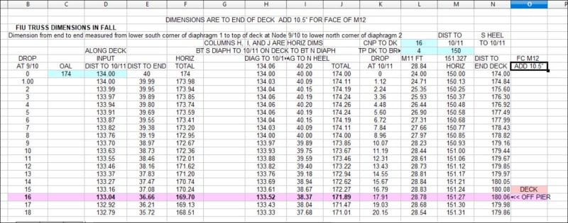
The calc considers rotation about the bottom corner of the south diaphragm and may fudge a bit because it projects drop at 10/11 as a ratio of horizontal distances relative to the drop at 9/10. I do not think that causes a variation that can be disproved by dash cam evidence.
It seems the base of M12 at the top of the deck is forced about 6 feet north before being pulled back.
If there is a need, I can change input lengths easily.
FIU_M11_THRUST_ufbdgf.jpg


EDIT OOPS!! Column N is final horizontal distance from south corner of Diaphragm 1 to the point on M12 where the top of the deck and the end of the deck coincide. That dimension was used as the distance to Node 11/12. To find the over all length add the 10.5" that M12 extends beyond the end of the deck. The heading on that column incorrectly notes :deck". The deck has literally "gone south".
 
waross (Electrical) said:
It will be interesting to see if you can calculate the interference between member 11 and the corner of the deck.

Drawing B-37 has dimensions of concrete at Node 11/12. Overall 6-4 1/2. The fillet is left behind - about 13" gone there. I am going to deduct the 10.5" projection of M11. That leaves about 4'-4" of construction joint (without the 10.5").
From the spreadsheet the deck is ready to depart the pylon when 9/10 has dropped about 16 feet. At that point the bottom of Node 11/12 has moved north about 6 feet, the separation is about 8 feet. The point where Node 11/12 joint clears the end of the M11 projection (Put the 10.5" back) is about 5'-2". That coincides with a drop of 9 feet at Node 9/10, where the deck likely 'folded'. That assumes the deck extension of 10.5" for M12 is still attached to the deck. So if I did it right M11 clears the deck while the deck is still on the pylon.
I think the deck area under M11 and M12 was sheared free and went north with M11 and M12. And that left a void for M11 to fall into, beginning where the "blowout" started. With M11 at 31 degrees, the 24" dimension becomes about 4 feet measured horizontally, and half the member is 2 feet. So if the break out developed at the mid line of M11 the 5'-6" slide required to clear the deck is reduced by 2' and becomes 3'-6" slide required to fall into the void in the deck. That corresponds to a drop of about 5 feet at Node 9/10 on the deck surface.
I expect there will be questions.


Thanks Vance. Nice work.
Am I reading your spread sheet correctly?
Does the 11/12 node move far enough north to drop off the north end of the pier?
Is it possible that there were two drops, one onto the top of the deck, and shortly after a second drop onto the top of the pier as the deck falls away?
Two consecutive drops followed by being dragged back onto the pier after hooking over the end of the pier would explain the damage to the lower ends of member 11 and member 12.

In regards to the action of the lower PT rod.
Has this been explored before I brought it up?
I can't remember seeing it in previous posts.
I see the lower PT rod acting as more than a simple pin.
It was at about a thirty degree angle.
It may have been acting as a wedge and exerting considerable downward force on the lower part of member 11.
Given the angle, the downward force would have been greater than the horizontal force.
This would have provided considerable clamping force to increase the resistance to sliding of the fractured concrete.
There is always a reluctance to examine new suggestions when your mind is made up. (Speaking generally, not to you personally Vance. I feel the same reluctance myself at times.)
The PT rod did not fail either in tension or in shear.
There has been speculation that due to the diameter of the sleeve, the PT rod did not make any contribution to holding the joint together.
I suggest that there is no evidence that the PT rod was centered in the sleeve.
I suggest that the position of the PT rod in the sleeve can be estimated by the 1/2"to 3/4" opening of the original crack.
The rod was there.
The rod was strong enough to make a difference, both in the horizontal plane, acting as a pin in shear and in the vertical plane, increasing the clamping pressure.
It was there, it must be accounted for.
Well, maybe not. There are a lot of things that FIGG didn't consider.


Bill
--------------------
"Why not the best?"
Jimmy Carter
 
If there is any credibility to my effort at a spreadsheet and the logic of the geometry, at a drop of 13 feet and more at Node 9/10 the north face of Node 11/12 is hanging beyond the north face of the pylon by maybe 8"(putting the 10.5" back into the picture) to a foot (11-1/2") max then drawn back to the south until the deck hits the roadway and everything stops. I see it as reaching the edge of the pier, extending beyond the edge, but not falling over the edge - in most any condition the remains could have cantilevered a foot or so.
I do not see two drops - it all began with Node 11/12 on and in contact with the surface of the deck.
Member 12 and the canopy it supports total about 50 kips. Member 11 is split and damaged in the last photo taken. It would seem that the weight of M12 would have to be supported by the lower face of M11 as it slid over the edge of the blowout zone. How much moment could M11 resist in the damaged lower section at Node 11/12? Post collapse photos show maybe 4 feet of the bottom end of M11 is gone. Answer - not enough,
apparently.
But - There could have been two drops - or a two step single drop. IF the bottom of the blowout block provided a surface for support - at the top of the 8" pipe sleeve. I have no good dimensions for the remaining surface on which the Node and blowout block could have been supported. Then there would be about a 24" drop to the top of the pylon as a second drop.
I suspect the bending caused by the lower face of M11 going over an edge coupled with the drop to the top of the pylon explains most of the damage to M11 during the collapse.

It may have been acting as a wedge and exerting considerable downward force on the lower part of member 11.
Early on, perhaps. But at some point it began ripping out the bottom. If it created a normal force because of the wedging it also created an opposite force against the deck surface from below and may have contributed to the cracking experienced as the blowout block failed. But as I recall the deck is not ruptured and remains in place just north of where the PT rod enters the deck.

I concur with your comments about the PT rod in the sleeve and the cracking in the deck. The possible contribution to failure or resistance/support provided is quite difficult to really determine. All told, there was apparently enough capacity at the deck surface to transmit a force sufficient to tear out the "blowout" block of the deck.

EDIT ADD A comment - the geometry and results are sensitive to the location of the break in the canopy and M11 at the top = was the hinge at the Node? Edge of blister? I cannot answer that.

 
Status
Not open for further replies.

Part and Inventory Search

Sponsor

Back
Top