Continue to Site

Eng-Tips is the largest engineering community on the Internet

Intelligent Work Forums for Engineering Professionals

  • Congratulations KootK on being selected by the Eng-Tips community for having the most helpful posts in the forums last week. Way to Go!

Miami Pedestrian Bridge, Part XIV 78

Status
Not open for further replies.

JAE

Structural
Jun 27, 2000
15,444
A continuation of our discussion of this failure. Best to read the other threads first to avoid rehashing things already discussed.

Part I
thread815-436595

Part II
thread815-436699

Part III
thread815-436802

Part IV
thread815-436924

Part V
thread815-437029

Part VI
thread815-438451

Part VII
thread815-438966

Part VIII
thread815-440072

Part IX
thread815-451175

Part X
thread815-454618

Part XI
thread815-454998

Part XII
thread815-455746

Part XIII
thread815-457935


Replies continue below

Recommended for you

Consider: The canopy was held together by multiple PT rods. Right.
The canopy broke in several places but the PT rods did not. I do not see evidence of the canopy breaking in several places until the deck hit the roadway and the collapse was basically complete.
As the canopy fell, the end to end distance shortened. I agree. But until Node 10/11 (or wherever the break in the canopy developed) fell thru a straight line from the bottom of the diaphragm 1 to the top of M12, it actually got a little bit longer. Then it began to shorten.
There is no way that member 12 could have remained vertical as the canopy fell. Agree.
As for the lower PT bar restraining the movement, Consider the amount of concrete that would have to be crushed for member 11 to fail in compression with the amount of concrete that would have to be crushed to relieve the restraint of the PT rod.
If I read this correctly, your point is the PT rod would have failed to resist the slide before a compression failure developed in M11. Am I correct?
The lower PT rod gave it up early as it tore from the bottom of M11. The upper PT rod went with the bottom of M11, lost all concrete around the anchor plate, and lays bare on the top of the pylon. So I see the lower PT rod as being the only one providing resistance. And as compared to the axial capacity of an undamaged M11 your point (as I read it) is correct.
As I view some videos it seems the canopy may have failed first - does anyone else see this? I welcome dissenting observations.

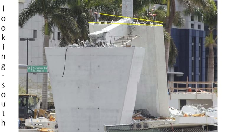
EDIT ADD Looking back to March 18 of 2018, the view from the south shows the unbroken length of the canopy as 4" on my monitor and 3.25" wide - with actual width being 16 feet the unbroken piece is about 20 feet long - about the distance to the north edge of the blister. The deck may have failed at the north face of the blister. Or my monitor is screwed up.


Wonderful graphics. The added outlines bring the movements of the members forward and into visual clarity.
I am going to suggest that had you chosen to release the joint between M11 and M10 and fixed the yellow outline of M10 to the image of M10 the yellow lines would have illustrated what happened to Member 11 more clearly.
By the third frame, as you see, the outline of Member 10 is shown trying to punch thru the deck.
The discussion of triangles should probably be expanded to include the canopy/M10/M9 triangle which I think was not damaged at the time the third image was captured. Outlines on M9 would illustrate any change in relationships by M9.
I am now thinking the canopy first failed at the north end of the blister. In the third frame, M11 was broken at Node 10/11 because Node 10/11 had dropped and Node 11/12 was still on top of the deck.
Is there any evidence that the canopy also failed at the south end of blister 10/11?
 
Adding to my previous post, and referencing the spreadsheet of a few posts prior, which considered the south section to be rotating about its bearing pad, because Node 10/11 is farther north than Node 9/10, Node 10/11 drops 1.12 times as much as Node 9/10. The canopy and deck slope from the north end according to their relative drops and their slopes are relative to the distance from the north end.
If we consider the vertical distance of Node 10/11 above the deck, at the point where Node 9/10 has dropped one foot and Node 10/11 has dropped 1.12 feet, the point directly below Node 10/11 has dropped 24'/40' X the one foot drop at Node 9/10 or 0.6 feet. The vertical distance between Node 10/11 above the deck has shortened by 1.12'minus 0.6 feet or 0.62 feet. The 'pancake' of Member 11 has begun.
 
Hi Vance. I have scrolled through so many times looking at pictures that I am loath to do it again.
I did look at a lot of pictures trying to answer than question and saw some suggestion that the first break was at the 10/11 joint.
With all the PT in the canopy, I doubt that they blister was strong enough to act as a fulcrum for a break.
The spot with the greatest force to strength ratio was the point at which the member 10 PT rods crossed the member 11 PT rods.
I may be wrong.
But, no matter where the canopy broke, member 11 would still be pushed to the north.
Revisiting another issue:
This assumes that the M12 Canopy joint held. I think multiple photos show it did not hold. Please remember that the M12 Canopy joint was a cold joint as well. The falling canopy put the joint in tension. It broke. As I said before, M12 followed the Canopy down.
I have spent a lot of time scrolling through this and previous threads.
I can not see any photographs showing any damage to the canopy to member 12 joint.
I appreciate the work that you spent isolating frames but I find them inconclusive.
The view is obstructed by a power pole and by a manlift boom.
Member 12 is obscured by shadows and blends in with the tree in the background.
Inconclusive.


Bill
--------------------
"Why not the best?"
Jimmy Carter
 
The vertical pin.
image_aqizxm.png

At first mention I had that sinking feeling, oops, I missed something important.
Then I looked further.
Construct-ability.
It appears that the pin is shown passing through the deck into the pier.
Tough to do when the pier is on site and the deck is being cast in the fab yard.
The pin would have to pass through the drain pipe.
There is no photographic evidence that there was a pin through the drain pipe.
And it is not shown on this rebar detail.
image_ly3uas.png

Conclusion: That vertical pin did not exist.


Bill
--------------------
"Why not the best?"
Jimmy Carter
 
I agree with your conclusion.
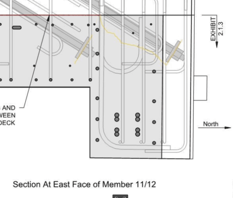
Drawing B-23 shows the vert PT rods as 1-3/8" dia, plate on bottom, 4 feet into pylon, with a coupler at the surface of the pylon.
There are 2 vert PT rods in the pylon, each 1'-1" from center of structure. That is 2+1/2" from the face of M12. So one of the sleeves on each side was there to access the coupling nut and install the rods post-erection. Note 4 of Stage 3 notes calls for the installation and stressing of the PT rods after grouting below the diaphragm.
I wonder if the PT tensioning equipment will fit that close to M12.

Previously, regarding damage to the canopy at M12, there is cracking and chipping of concrete below the surface of the deck at M12. I first thought there was no damage also. There is at least 2 feet of translation discontinuity of Member 12 - so bending, shears, and moments are created. Clearly the damage is far greater at the deck end of M12, but the top to deck is not undamaged. Whether that damage happened at the beginning of the collapse or near the end, is another matter and difficult to determine. EDIT ADD Sorry - did not intend to jump onto this - I had not seen SFCharlie's post of the picture when I sent this. Maybe the comments will have some value.


Vance Wiley (Structural)19 Jul 20 16:41 said:
The discussion of triangles should probably be expanded to include the canopy/M10/M9 triangle which I think was not damaged at the time the third image was captured. Outlines on M9 would illustrate any change in relationships by M9.
I am now thinking the canopy first failed at the north end of the blister. In the third frame, M11 was broken at Node 10/11 because Node 10/11 had dropped and Node 11/12 was still on top of the deck.
Is there any evidence that the canopy also failed at the south end of blister 10/11?
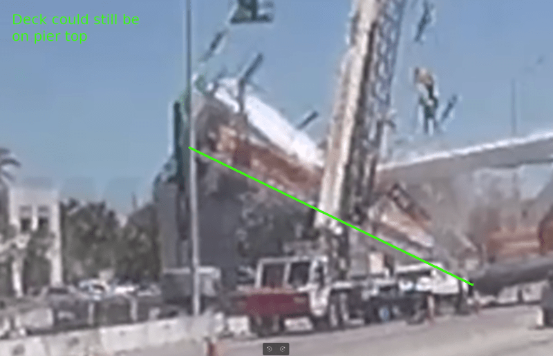
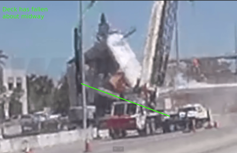
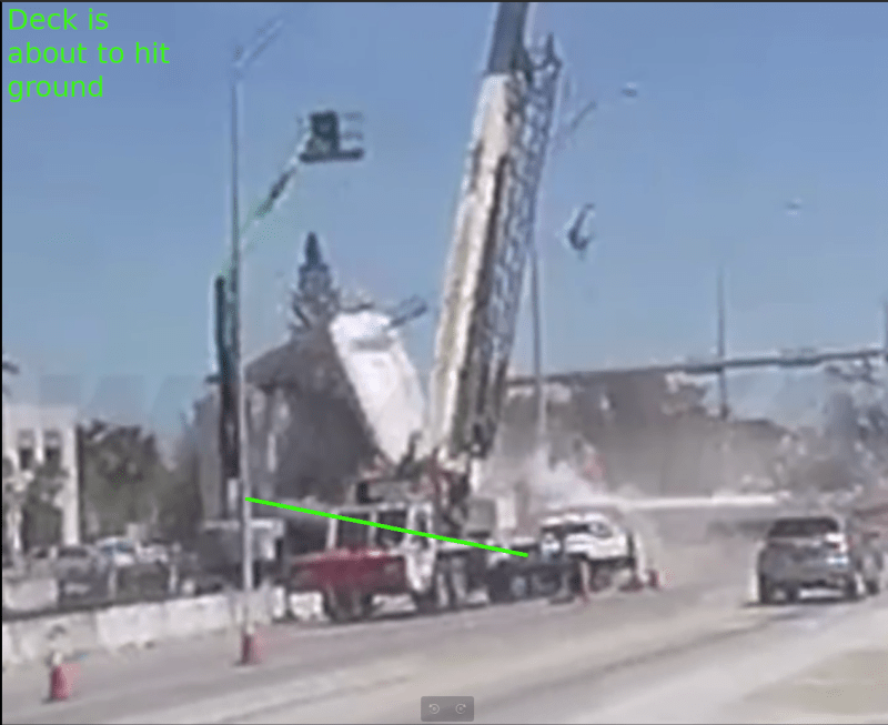
So I made a first attempt; a very rough draft if you will; the jpgs should probably be best view in some tool that will allow you to zoom in and then look at the next jpg with the same position and zoom. There are three triangles; one locked to M12, one locked (more or less) to M11, and one locked to M10.
Any help suggesting a better presentation will be appreciated!
I also ran into difficulties due to the dashcam "dollying". I need some sort of 3D model, but I don't know how to even start...

SF Charlie
Eng-Tips.com Forum Policies
 
 https://files.engineering.com/getfile.aspx?folder=a2685506-a97f-47e5-bf3d-4b8977b94e7c&file=fiubridgecollapsedashcamfullspan.zip
Thanks Charlie.
Nice work.
The slides suggest that the first break in the canopy may have been at the north end of the blister.
Suggestive but inconclusive.
If the canopy first broke at the north end of the blister it is likely that the upper end of member 11 also broke.


Bill
--------------------
"Why not the best?"
Jimmy Carter
 
waross (Electrical)21 Jul 20 01:07 said:
If the canopy first broke at the north end of the blister it is likely that the upper end of member 11 also broke.
Yes! in fact, I would not be able to prove from the video that the top didn't break first. It is just the mechanics that suggests the bottom of M11 broke first.

SF Charlie
Eng-Tips.com Forum Policies
 
Great work.
After looking at the images I have a comment. Or two.
As I study Frame 3 I think the top edge of M11 is a place to focus. Even though the crane is in the way, we can see the top edge of M11 that is visible will project to intersect the bottom of the canopy some distance - maybe 5 feet - north of where M10 intersects the canopy. Drawing B-37 has the overall contact distance as 4'-2" but that includes small fillets at each side. And we may not be seeing exactly where the bottom of the canopy really is.
Now to Frame 4 - notice the projection of the top of M11 almost touches the deck at the same place as the top of M10? Drop of the canopy looks like about 4 feet.
Frame 5 - more of the same - not a lot of difference from Frame 4. Top of M11 projects to almost same point as top of M10 at bottom of canopy. Drop estimate is 6 feet. Important point - top of canopy and M12 have dropped maybe two feet. Deck is still on top of pylon.
Frame 6 - Top of M11 is projected to two feet or more down M10 below the canopy. This suggests M11 has separated from Node 10/11 at this point. In fact, it appears the top of M11 projects to intersect the deck maybe 80 feet to the south. The top of the canopy at M12 is now dropped maybe 4 feet or more. Total drop is maybe 8 feet or more. Deck appears to be on top of pylon. This frame and Frame 7 have two intersecting lines at the left end which, in Frame 6, appear to be a projection of the canopy and M11 - are these construction lines and not something popping out of the construction?
Frame 7 - The canopy looks to be folded about at the left side of the white crane boom. Node 9/10 has about hit the roadway. Is the deck still on top of pylon?
Thanks for the great work.
 
waross (Electrical) said:
If the canopy first broke at the north end of the blister it is likely that the upper end of member 11 also broke.

You are flogging a dead horse now.

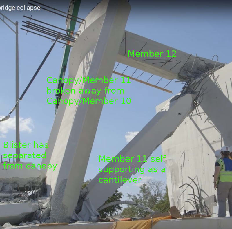
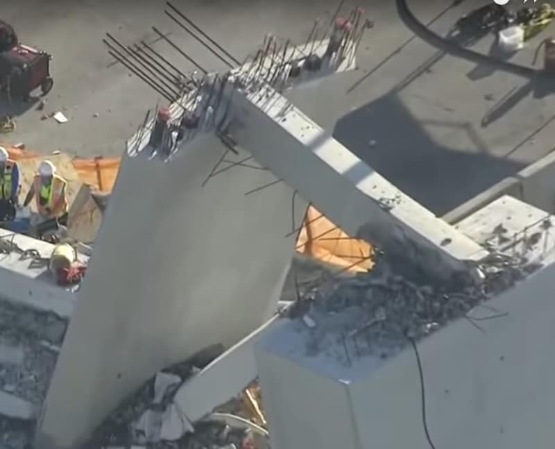
Upper end of member 11 may have been damaged but did not break. The photo below shows upper end of member 11 was able to act as a fixed support of a cantileve after the collapse. The free end of the cantilever (member 11) has rebar resting on on the pier but they were not bent suggesting member 11 was able not to relying the pier as a support. You can search videos of NTSB engineers milling around underneath member 11 never feeling any safety issue.

Member_11-12-canopy_after_collapse1_zbjiu8.jpg


Any engineer with the basic understanding of statics can tell us that if the member 11 were unable to hold its position at the bottom with the deck but move to the north then the whole bridge will collapse.

Equally if the upper end of member 11 move vertically above the canopy the bridge will also drop.

The evidence in the field is member 11's upper end has not moved upward but was still solidly connected to the canopy as shown from the above photo. In the collapsed bridge the canopy folded or hinged at the point member 11 meets member 10. The blister simply came off from the canopy with possibly some rebar attached.

The important feature of the bridge is member 11 is a strut. As long as member 11 does not crush or buckle in compression and the two ends are structurally connected it will be able to "prop" up the bridge.

All the evidence in the field and the official reports from MCM, FIGG, OSHA and NTSB indicate the bridge failed because of 11/12/deck connection.

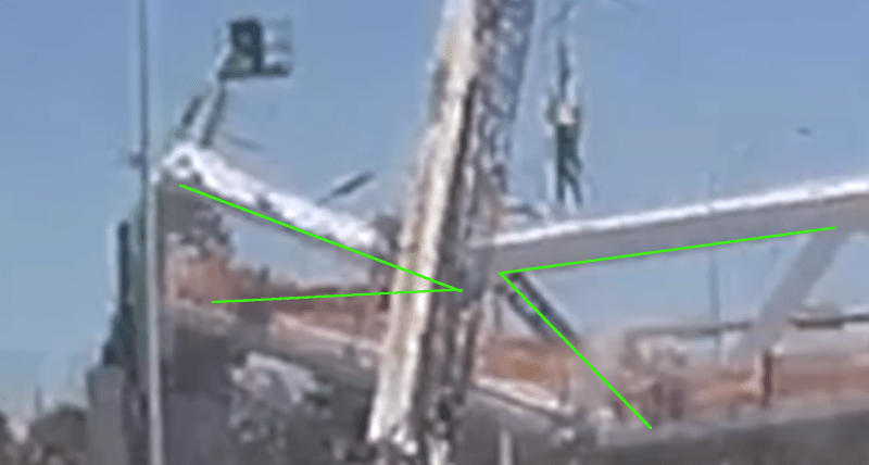
Yet the discussions that something fishy happening at the canopy joint amount to nothing but video footages confirming the canopy hinge deflection being more pronounced than that of the hinge at the deck. This has been pointed out that top of member 11 might have separated from member 10 at the canopy during the fall. I post a similar shot taken by another vehicle (I believe) showing the separation.

a2_cbwrik.png


All post-collapse photos show the canopy has been broken up at this location. Only the breakage took place during the collapse could explain why Member 11 was able to attached to the canopy and ended up as cantilever on the ground.


Vance Wiley (Structural) said:
The canopy looks to be folded about at the left side of the white crane boom. Node 9/10 has about hit the roadway. Is the deck still on top of pylon?

a3_thc8w9.png
a5_exvang.png
a6_jpykh9.png
 
A different perspective:
Saikee's first photo above, The upper PT rod appears to be supporting member 11.
Saikee's third photo above, Member 12 is shown still at right angles to the canopy.
It appears that member 11 has broken at the upper end.
We can agree to disagree.
Blame parallax and poor quality frames.

Bill
--------------------
"Why not the best?"
Jimmy Carter
 
I don't agree that member 11 was still attached at the canopy end after the collapse either.
 
Lionel said:
I don't agree that member 11 was still attached at the canopy end after the collapse either.
I agree with Lionel.

[link ]Bill[/url]
--------------------
"Why not the best?"
Jimmy Carter
 
It's a frustration in describing this event because it was a semi-monolithic concrete casting with various levels of internal rebar reinforcement. Except for looking at cold joints, where one member ends and another begins is vague, and when the concrete fails, but the reinforcement remains continuous, does it mean a member is detached or is still attached? Likewise when a relatively rigid body fractures, it has to fail at multiple points simultaneously; the description of what failed first is difficult to point to. And is it still a member when nearly half of it is ripped off?

I'd say the upper end steel that bridged between the canopy and member 11 was largely intact. But is 11 still attached? I guess it depends on whether the rebar in 11 is considered part of 11. It's clear that all the rebar in 11 joining it to the deck was either severed or torn loose and the concrete at that joint was pulverized, so that joint clearly no longer exists.
 
Status
Not open for further replies.

Part and Inventory Search

Sponsor