Continue to Site

Eng-Tips is the largest engineering community on the Internet

Intelligent Work Forums for Engineering Professionals

  • Congratulations KootK on being selected by the Eng-Tips community for having the most helpful posts in the forums last week. Way to Go!

Miami Pedestrian Bridge, Part XIV 78

Status
Not open for further replies.

JAE

Structural
Jun 27, 2000
15,460
A continuation of our discussion of this failure. Best to read the other threads first to avoid rehashing things already discussed.

Part I
thread815-436595

Part II
thread815-436699

Part III
thread815-436802

Part IV
thread815-436924

Part V
thread815-437029

Part VI
thread815-438451

Part VII
thread815-438966

Part VIII
thread815-440072

Part IX
thread815-451175

Part X
thread815-454618

Part XI
thread815-454998

Part XII
thread815-455746

Part XIII
thread815-457935


Replies continue below

Recommended for you

And I have not forgotten your observations. They will likely bother me for some time.
Did anyone report any cracking at Node 10/11? If I had a rattlesnake at my foot I would not be looking up either. In this case the rattlesnake would be the cracks in the deck.
We have so little if any information on the top of Member 11. The photo that I recently saw for the first time shows the lower end of M11, - I think.
The question arises - if Member 11 failed at the top how was it able to deliver enough load to the deck to cause the blowout?
As far as forces go, Member 11 pushes south at the top just as much as it pushes north at the bottom. But it is near the end of the deck at the bottom. The Nodal shear at 10/11 is greater because Member 10 is also pulling to the south at the same time and those components are additive. The canopy is only 12" thick but the blister is a reinforcing element to lower the stresses of the transfer of the force. BUT - there is a FIGG/MCM construction joint there also.
At this point Node 11/12 seems easier to explain and has more evidence to support it as the initial failure. But that is no reason to stop looking. Thanks, Charlie.
 
Vance said:
the geometry and results are sensitive to the location of the break in the canopy and M11 at the top = was the hinge at the Node? Edge of blister? I cannot answer that.
That is a very good point, and as you say the location affects the results of the geometry.
I am going to think about this for awhile.

Bill
--------------------
"Why not the best?"
Jimmy Carter
 
After the collapse: the blister remains with the level portion of the canopy. M11 is diagonally upright with upper PT rod in M12. M12 is horizontal at about 90 degrees to the North end of the canopy vertical, with damage to the M12 canopy joint.

SF Charlie
Eng-Tips.com Forum Policies
 
Can you get a probable length of the north segment of the canopy from the last photo you posted? It looks to be about the same length as the height of the pylon. The deck had a formed curb so that is a consideration in that view.
 
Speculation:
The blister is probably another instance of good concrete and a lousy construction joint.
The blister looks as if it parted company with the canopy and is probably not in the original position relative to the canopy.
We can't discount the action of the PT bars in member 10 that may have pushed the blister to the north.
For discussion rather than argument, the canopy may have broken in two places.
I am wondering about the length relative to the height of the pier.
Intuitively, the weakest spot and the spot with the most bending would be under the blister where the PT rods from members 10 and 11 cross.
This is also a corner of the triangle.
Breaking of the canopy away from the 10/11 joint would destroy the geometry of the triangle.
It is hard to imagine that the obvious break in the canopy is the original break, given that the canopy to member 12 joint is intact.
Please consider this sequence as a possibility.
1. The bridge starts to fall as we have discussed and the canopy hinges at the 10/11 node. That would tend to lift the blister off of the canopy, intact.
2. As the bridge falls, the lower ends of members 11 and 12 are destroyed.
3. When the broken end of the canopy hits the ground, the canopy breaks again, and also breaks member 11.
Looking at the last picture posted; The first break would be the south side of the section of canopy labeled 'CANOPY" and the second break would be the north end of the section labeled "CANOPY".
Part of member 11 would be broken and beneath the broken canopy.
Consider the length of the PT bar compared to the intact length of member 11.
That argues strongly for a section of member 11 to be broken and lying beneath the rubble of the canopy.
I find it difficult to accept the damage to the lower end of member 11 to crushing damage. This is a triangle and crushing of member 11 would change the geometry and change the angle of the canopy to member 12 joint.


Bill
--------------------
"Why not the best?"
Jimmy Carter
 
waross (Electrical)15 Jul 20 22:33 said:
given that the canopy to member 12 joint is intact
Sorry to be so blunt about correcting you, but a few parts back, one of the primary members of this thread found a picture that made it very clear that the column 12 canopy joint had broken and only by luck come back to it's original angle. Also, the video clearly shows the canopy falling while M12 remained vertical. I measured the angles between the members frame by frame. (and Yes, M11 had to become shorter for this to happen, it does!)

SF Charlie
Eng-Tips.com Forum Policies
 
SFCharle, do you remember where that video is? Thanks.

Bill
--------------------
"Why not the best?"
Jimmy Carter
 
Thank you SFCharlie.
I have now looked at that several times and stepped through it several times.
It is not as clear as one would desire.
There is a utility pole in front of member 12 and a tree behind member 12.
Member 12 is being shaded by the canopy and is difficult to make out.
What at first looks like member 12 may be the unshaded utility pole.
Add to that the moving viewpoint.
There are several frames per second.
In the last frame in the 23 second interval, it is unclear to me which is the tree behind, which is the utility pole in front or which is member 12.
In the next frame, the 1st frame in the 24 second interval, it arrears that member 12 is still attached to the canopy at right angles.
Looking at the photograph of the canopy and member 12 in their final resting positions, it is hard to accept that gravity would allow them to remain in that position if the connection between the canopy and member 12 was broken.
Member 11 seems to be broken at both ends and does not seem to be providing any support.
I may be wrong.
Please take another close look at the video with consideration of the utility pole, the tree in the background, the movement of the camera and the shadows.
Thanks.

Bill
--------------------
"Why not the best?"
Jimmy Carter
 
waross (Electrical)16 Jul 20 20:43
Yes! It is very hard to sort out all the pieces. I was able to get advice from the great gentlemen of this thread, to dump out the individual frames of this video. I used an old windows seven computer to enhance them. I drew lines around each member in each frame of the collapse and copied them to the next frame so I could detect motion and rotation. I believe you are right, that M11 broke at both ends. I also believe that M12 remained upright until it started to follow the canopy in falling south.

SF Charlie
Eng-Tips.com Forum Policies
 
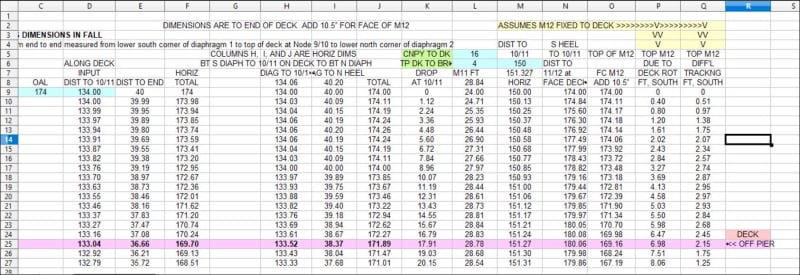
Since we are looking this direction, I added some columns to the spreadsheet for geometry.
I can't tell if M11 failed and shortened or how much it may have shortened. But if the triangle "canopy/M11/M12" was lost, for whatever reason, the location of the top of M12 is influenced by the deck rotation as Node 9/10 drops and by the rotation of the canopy as Node 10/11 drops.
Added column "Q" shows the eepected difference in position due to the mistracking of the geometry - in feet. That difference is accommodated by 1) strength of joints and M12 or 2) cracking in M12 or 3) failing of joint to canopy or deck or both.

FIU_SS_DROP_M12_ADD_sbyu0k.jpg
 
Consider: The canopy was held together by multiple PT rods.
The canopy broke in several places but the PT rods did not.
As the canopy fell, the end to end distance shortened.
There is no way that member 12 could have remained vertical as the canopy fell.
As for the lower PT bar restraining the movement, Consider the amount of concrete that would have to be crushed for member 11 to fail in compression with the amount of concrete that would have to be crushed to relieve the restraint of the PT rod.

Bill
--------------------
"Why not the best?"
Jimmy Carter
 
waross (Electrical)17 Jul 20 18:36 said:
There is no way that member 12 could have remained vertical as the canopy fell.
This assumes that the M12 Canopy joint held. I think multiple photos show it did not hold. Please remember that the M12 Canopy joint was a cold joint as well. The falling canopy put the joint in tension. It broke. As I said before, M12 followed the Canopy down.
 
Status
Not open for further replies.

Part and Inventory Search

Sponsor