Eng-Tips is the largest engineering community on the Internet

Intelligent Work Forums for Engineering Professionals

  • Congratulations waross on being selected by the Eng-Tips community for having the most helpful posts in the forums last week. Way to Go!

Miami Pedestrian Bridge, Part XIV 78

Status
Not open for further replies.

JAE

Structural
Jun 27, 2000
15,433
US
A continuation of our discussion of this failure. Best to read the other threads first to avoid rehashing things already discussed.

Part I
thread815-436595

Part II
thread815-436699

Part III
thread815-436802

Part IV
thread815-436924

Part V
thread815-437029

Part VI
thread815-438451

Part VII
thread815-438966

Part VIII
thread815-440072

Part IX
thread815-451175

Part X
thread815-454618

Part XI
thread815-454998

Part XII
thread815-455746

Part XIII
thread815-457935


Replies continue below

Recommended for you

The necessary condition for the Lower PT rod to rip out of 11 is thet 11 has to move further north for that to occur. Also there would be some initial deformation of the shear ties in 11 that would delay the onset of the rip so I would wager that the rip occured later in the cascade.

Regarding the shear plane in 12, it is not an epic saber slice from the heavens. It is the expression of the tensile stresses built up from the bending deformation and was to be expected but was never identified. There are many vids of beam shear failure on the net and its easy to see the amount of abuse a beam will take (include deflection) without an epic complete failure. Hence, I wager that 11 lost its ability to support its compressive load first.

In essence, the failure is a complex arrangement of simple, well understood failure mechanisms with a wicked feedback loop.

3DDave, I will gave you a star because I like the diagram.

I can"t compete with Vances artistic abilities. I swear if I drew mouse ears on one of my sketches, some people would never get over it, even if they know the bridge design was mickey mouse.
 
Vance Wiley (Structural)

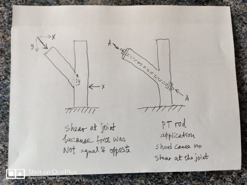
I suppose you can create shear at the joint as your 6 Jul 20 01:42 post depicts.

I am think alone the line more like below.

a574b42e-af0b-41c9-9419-fa208112b614_xoqiwx.jpg
 
My interpretation of the event is quite simple.

The bridge was still standing but with worrying cracks described by the workmen "crack like hell". At this point the two PT rods in 11/12 have been de-stressed as per design.

11/12 was holding and could possibly for able to do so for weeks and not days. I support this statement by pointing out the shift of 11/12 was still relatively small according to the crack measurements at that time. The rebar across the shearing plane, as one shown by NTSB Fig 32 based on the failed bridge evidence, has possibly yielded at a few locations but not broken or snapped.

Personally I think the 11/12 was held in position by the vertical reinforcement inside Member 12 as it is quite substantial with 2x#11 and 8x#7 which if you like were acting as dowels. It is noteworthy to point out none of these vertical reabr has failed in the end. They were just stripped of the concrete an clear indication of bond failure.

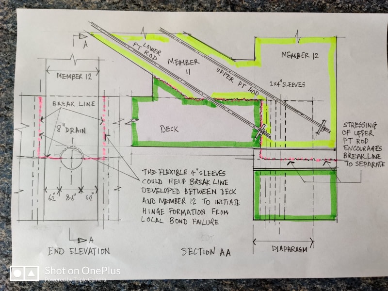
In my own opinion the re-stressing of the PT rods was the the last straw that broke the camel's back. First by attempting to pull the cracked 11/12 joint together the restressing woul grind smooth the shearing surface, reverse the bearing concrete stress from back to the front of the rebar, asymmetrically pull the 11/12 shearing face with the deck as only one PT rod was stressed at a time and lastly the upper PT rod could literally pull open the north part of the shearing face due to the eccentricity.

1a79ea6f-9492-45a2-86de-a79c5d30997e_l9yozb.jpg


I am highly critical of the proximity of the two 4" vertical flexible sleeves on either side of Member 12 as they are ideal instruments for crack inducements. The substantial verical rebar inside Memeber 12 have the thinest concrete cover next to the vertical sleeves which are almost certainly the initiation location for a blowout. The bond between Member 12 vertical rebar and concrete was forcibly reversed by destressing/restressing at the two points of thinnest cover is a bomb waiting to go off. The bond between concrete and steel must be totally rigid if two were to have same strain so destressing/restressing movements are simply cannot be tolerated. Once the steel and concrete each has its own deflection the bond is gone!

Therefore it is possible a bond failure local to the 2 No. of 4" flexible on either side of Memeber 12 increased the flexibility of the 11/12 hinge with the deck sufficiently to initiate a blowout. The record shows the bridge collapsed "during" the last operation of restressing the bottom PT rod after the upper PT rod had been fully re-stressed.
 
Early on the concrete failed and a crack opened up.
At that point all that was holding the joint together was the rebar.
Given the relative movement of the joint, the rebar must have been compromised.
Why did the joint not fail completely?
After moving over 1/2 inch, why did the movement stop?
The lower PT bar was restraining further movement.
The lower PT bar would have been forced against the bottom of the sleeve.
The lower PT bar was not tight in the sleeve and some movement relative to the sleeve was possible.
The lower PT bar did not act as a restraint until it had taken up all possible movement within the sleeve.
I submit that the initiating blowout was the failure of the bottom of member 11.
When the bottom of member 11 blew out downwards due to the increased force against the restraint of the lower PT bar the 11/12 node was relatively free to move away from the deck.
The rebar had been unable to prevent the original failure or separation and was no compromised.
Without the restraint of the lower PT bar, the rebar provided little restraint as the failure progressed.
Consider:
1. The lower PT bar never failed.
2. The lower PT bar was firmly anchored in the deck below the plane of separation.
3. The PT bar remained anchored in the deck.
4. The 11/12 node could not move away from the deck as long as the lower PT rod was in place.
The first blow out must have been the failure of the bottom part of member 11 as the PT rod started to rip out.

Bill
--------------------
"Why not the best?"
Jimmy Carter
 
waross (Electrical)

You may not be familiar with the design. The two PT rods are what we normally call "temporary work". It is there temporary to assist the constrcution and could be removed when the bridge is in service.

The bridge in service will have Member 11 permanently in high compression so it makes no sense to stress the PT rods there. However when the bridge was moved from the casting yard to the piers it could only do so by supporting the two "next" inner bays during the transportation so that the two end bays can be launched onto the piers. In this arrangement the end bay is a cantilever and Member 11 will be in tension. For this reason alone FIGG had to stressed the Member 11 for the purpose of transferring the structure from the cast yard to its final position. Naturally once in the final position the PT rods could be de-dtressed as happened on site.

My point is the two PT rods were never a permanent design and can be ignored in the strength assessment of the bridge in performing its structural duties in service.

Also the PT rods are straight bars of 1.75" diameter and they would not have been forced against the bottom of the sleeve before the collapse.

Early on the concrete failed and a crack opened up.
At that point all that was holding the joint together was the rebar.
Given the relative movement of the joint, the rebar must have been compromised.
Why did the joint not fail completely?

The 11/12 joint at that time, in the permant position with PT rod stress removed, had probably shifted by 1/2". Such deflection would not necessarily cause a failure. The rebar could be bent or even yielded at some locations with some local concrete crushing confined only to the area around the shearing plane that has shifted.
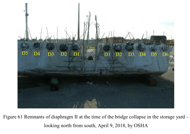
F61_lyxgnn.png


In the above OSHA Fig 61 there are 2x1.375" plus 8x0.875" vertical reinforcementcast inside Member 12 now exposed between the two D1 tendon anchors. It is my belief that these 10 steel reinforcement were acting as dowels to hold 11/12 in position prior to the collapse.

In engineering we learn from mistakes. One of the most valuable lessons of the FIU bridge is that there was not a single failure from the above 10 vertical steel bars when Member 12 sheared across them completely. There is no better illustraion to show the FIGG's design deficiency in not able to make these bars to do what they were supposed to.

1. The lower PT bar never failed.
2. The lower PT bar was firmly anchored in the deck below the plane of separation.
3. The PT bar remained anchored in the deck.
4. The 11/12 node could not move away from the deck as long as the lower PT rod was in place.

I do not have the dimension of the tube casing for the PT rod but my guess it would be around 4" so leaving at least 1" clearance all round the PT rod. In my experience it is highly probable when the concrete sheared by as much as 1" across the duct the Member 11 would have failed or broken already.

The 11/12 finally moved away from the deck. The lower PT rod anchor was still in its designed position with the deck. The upper PT rod was still inside Member 11. Member 11 was ripped open by pulling the lower PT rod against its bottom face where the concrete cover is at its thinnest. You can image between a 1.75" diameter high strength PT rod and a layer of say 3" concrete which one break first.
 
saikee119
You have obviously misunderstood my post.
When the joint failed, why did the 11/12 node move just one inch and then stop?
The tension was relieved from the lower PT rod.
The only function now provided by the lower PT rod was that of a pin, preventing further movement, until the tension was re-applied, generating enough force on the bottom part of member 11 to destroy the bottom part of member 11 and probably cause collateral damage to the upper part of member 11.
Please explain how the 11/12 node could move more than one inch without either breaking, pulling loose from the deck or breaking out of member 11.
The upper PT rod was completely contained within member 11 and played no part in the failure.
The lower PT rod had issues.
It was anchored at one end at the top of member 11.
It was anchored at the other end in the deck.
It crossed the plane of failure.
Tension in the lower PT rod would cause opposing forces between member 11 and the deck in the direction of the failure.
When the joint moved, the lower PT rod was forced against the bottom of the sleeve.
How could it not be so?
The rebars failed to remain embedded in the concrete, while the PT anchor did remain embedded.
Sounds like a failure of the reinforcing design to me.

Bill
--------------------
"Why not the best?"
Jimmy Carter
 
waross (Electrical)

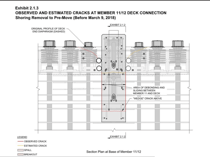
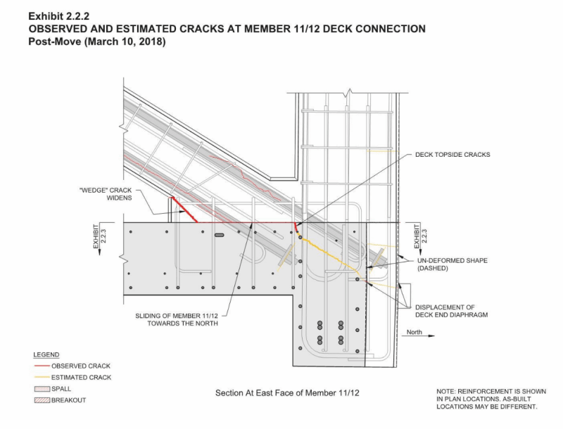
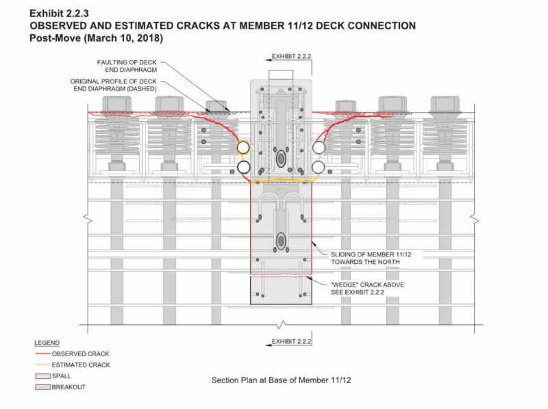
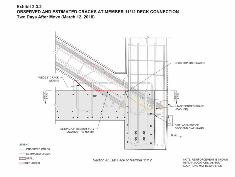
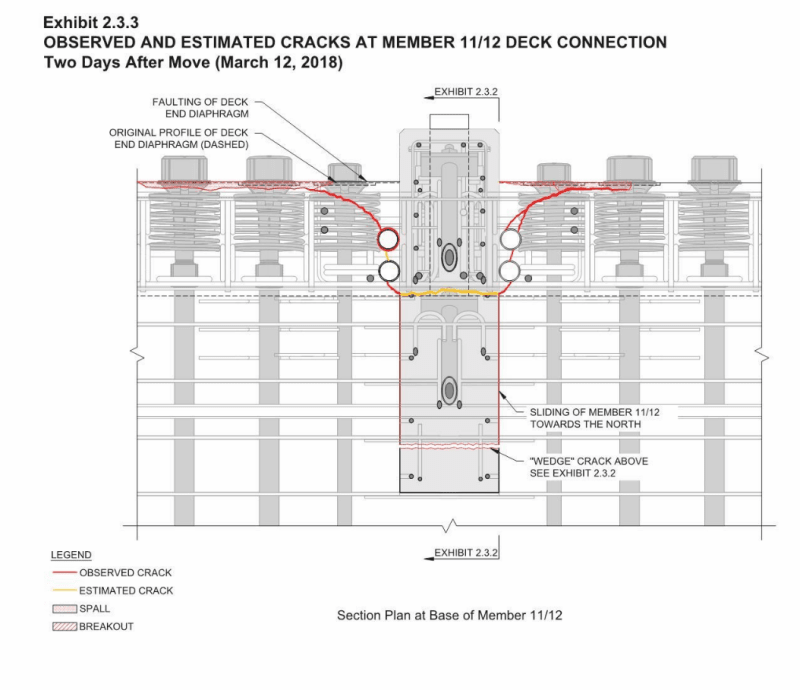
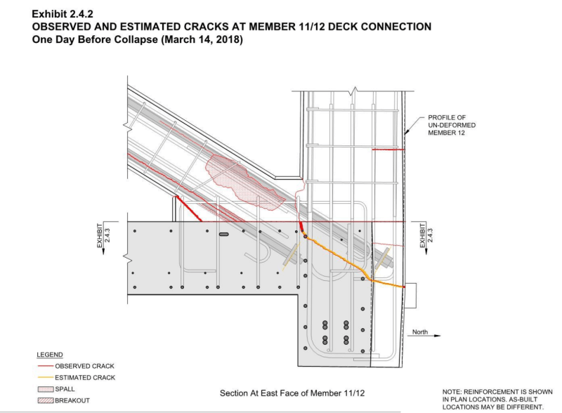
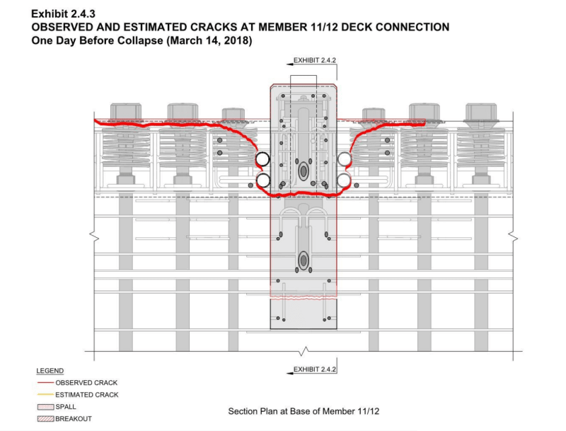
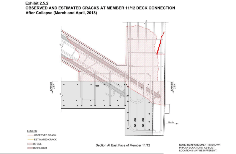
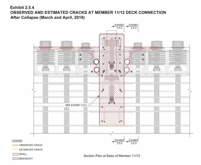
I suggest you have a read of WJE's sketches enclosed in FIGG report to see how the 11/12 developed the cracks and why it could remain in place until the day of collapse.

I suggest you take note of the reinfrcement, drawn to scale, along the failure surface.

The only thing you need to watch out in WJE's work, as it was used to fend FIGG, is the assumed cracked line marked in yellow. That we can agree or disagree. The rest is as per documented photos so should be credible.

ex2.1.2_elev_shoring_removed_hdrguu.png
ex2.1.3_plan_shoring_removed_kddiwt.png
ex2.2.2_10_Mar_elev_pgggaf.png
ex2.2.3_10_Mar_plan_ifsapr.png
ex2.3.2_12_Mar_elev_pehwe4.png
ex2.3.3_12.Mar_plan_a8hgrf.png
ex2.4.2_14_Mar_elev_mopvjr.png
ex2.4.3_14_Mar_plan_njgg1p.png
ex2.5.2_post_collapse_elev_cef9sk.png
ex2.5.4_post_collapse_plan_gsc7ul.png
 
saikee119
Thank you for the considerable time that you have expended relying to me.
Allow me to retract an ill advised sentence in my previous post.

Consider the following possible sequence.
The crack originated in the fab yard, either during or after the tensioning of the lower PT rod.
The joint was broken but substantially held in place by the rebars.
When the bridge was placed the crack opened up approximately 1 inch.
With one inch displacement through the lap joint of the rebars the integrity of the rebars was substantially lost.
Further movement was restrained by the lower PT rod acting as a pin.
I take issue with your estimate of the sleeves as 4 inches in diameter.
I cannot find a spec, but one picture seems to show the sleeve at about 150% of the rod diameter.
The sleeve may have floated upwards against the bottom of the PT rod in the wet concrete.
If the rebar lap joint could not prevent 1 inch of movement it could not have halted further movement.
It would have broken its bond with the concrete during the first movement.
When the crack opened it relieved the tension on the lower PT rod.
When the lower PT rod was retensioned, it forced the joint apart.
As the PT rod was acting as a restraint at that time, that restraint had to be relieved by the bottom of member 11 breaking out.
As far as the fall ripping the lower PT rod out, during the first part of the fall the angle between member 11 and the deck is diminishing, rather than increasing.
This would not have ripped the PT rod out of member 11.
The bottom of member 11 had to relieve the PT rod for the movement of the 11/12 joint to increase beyond the previous 1 inch.

1. Original failure in the fab yard, with movement restrained by the rebars.
2. Second failure when the crack opened up about 1 inch and destroyed the bond and integrity of the rebar lap joints.
3. Final failure when reapplied tension on the lower PT rod simultaneously broke out the bottom of member 11 and pushed out the 11/12 node.
Full length rebars would provide considerable restraint even after a 1 inch relative movement.
Similar movement on the lap joint would act to break the bond of the bars to the concrete and destroy the greater part of their effectiveness.
I believe that you are putting too much faith on the rebar lap joint and are not at all considering the action of the PT bar as a pin.


Bill
--------------------
"Why not the best?"
Jimmy Carter
 
waross (Electrical)

Consider the following possible sequence.
The crack originated in the fab yard, either during or after the tensioning of the lower PT rod.
The joint was broken but substantially held in place by the rebars.
The joint wasn't broken. It had some cracks. Every structure of this size and complexity will have cracks.

When the bridge was placed the crack opened up approximately 1 inch.
With one inch displacement through the lap joint of the rebars the integrity of the rebars was substantially lost.
Further movement was restrained by the lower PT rod acting as a pin.
The bridge was placed on piers on 10 Mar. PT rod tensions in 11 was removed within a few hours on the same day. Photos were taken on 12 and 14 Mar. Earlier photos show smaller cracks. Only on 14 Mar the crack was measured 1" on the outside but the interior was about 1/2". I urge you not to treat the PT rod as a structural element beccause within 11 it has no structural duty after destressing

I take issue with your estimate of the sleeves as 4 inches in diameter.
I cannot find a spec, but one picture seems to show the sleeve at about 150% of the rod diameter.
The sleeve may have floated upwards against the bottom of the PT rod in the wet concrete.
This is pure speculation. Do you have proof of such bad workmanship? Such accusation is very dangerous if unfounded.

If the rebar lap joint could not prevent 1 inch of movement it could not have halted further movement.
It would have broken its bond with the concrete during the first movement.
When the crack opened it relieved the tension on the lower PT rod.

You obviously lack the basic knowledge of reinforced concrete design. We are talking about a rebar perpendicular to a shear plane here. The bar has to be designed with a development length, approximatly 45 times its diameter, below and above the shearing face in order for the steel stress fully developed. A mear 0.5" lateral deflection of the bar inside a locally crushed concrete is not a big deal because rest of the bar can hold the structure if the situation deterioates no more. We are talking say about one diameter high of the steel and crushed concrete shifted by 0.5" but the rest of the length of 89 times the diameter is still soundly gripped by concrete. Here I urge you not to mention the PT rod because the 0.5" shift was the result of destressing. The 11/12 could have nearly negligible or not-measurable cracks prior to the destressing but nobody knows because the stress was removed from 11 within hours it was placed on pier.

When the lower PT rod was retensioned, it forced the joint apart.
That is pure speculation again and suggests FIGG didn't know about the bridge more than you. It is obvious to everyone that FIGG was tightening the PT rod to close the cracks and not to force the joint apart. I believe nobody knows whether the cracks were closed up or pulled further apart as the result of the restressing. We only know from OSHA report "They had re-tensioned the upper bar to the desired tension of 280 kips and were at the lower bar at their last cycle to complete 280 kips when the incident occurred."

As the PT rod was acting as a restraint at that time, that restraint had to be relieved by the bottom of member 11 breaking out.
As far as the fall ripping the lower PT rod out, during the first part of the fall the angle between member 11 and the deck is diminishing, rather than increasing.
This would not have ripped the PT rod out of member 11.
The bottom of member 11 had to relieve the PT rod for the movement of the 11/12 joint to increase beyond the previous 1 inch.
Can i ask you to read my post on 19 Jun 20 12:14 in which I drew two CAD sketches to explain how the lower PT rod was ripped out?


1. Original failure in the fab yard, with movement restrained by the rebars.
2. Second failure when the crack opened up about 1 inch and destroyed the bond and integrity of the rebar lap joints.
3. Final failure when reapplied tension on the lower PT rod simultaneously broke out the bottom of member 11 and pushed out the 11/12 node.
Full length rebars would provide considerable restraint even after a 1 inch relative movement.
Similar movement on the lap joint would act to break the bond of the bars to the concrete and destroy the greater part of their effectiveness.
I believe that you are putting too much faith on the rebar lap joint and are not at all considering the action of the PT bar as a pin.
For (1) Please understand that you cannot use the word "failure" here. As an engineer you should be prepared being on on a stand in the court of law when giving out such opinion. I have said it before contracturally no one could reject MCM's work at the casting yard. You can complain and MCM would just ask a labourer to brush-paint the crack areas with a cement slurry. You can inspect it later and wouldn't find anything. I am not suggesting it is OK for MCM to cheat but the cracks were just one grade above trivial because such cracks are fact of life in the industry especially if the work is stressed in one part and not the other.
For (2) There is no second failure. The 0.5" crack was recorded one day before the collapse. No more photos on it was taken. Like I said previously the bar has 45xdiameter above and below the shearing plane. Your destroyed bond can only about 1 to 2 diameter at the crack interface.
For (3) If you look at any of the OSHA photo on the lower PT rod you should find none of them show broke out the bottom of 11 but attched firmly to the deck. Also whenever bars were provided they were in fully length. The problem here is FIGG cannot insert them at the right places due to congestion. Please be advised suggesting the PT rod useful as a pin is irrelevant. Even if both PT rods could act as pins they were useless against the collapse because none of them broke.
 

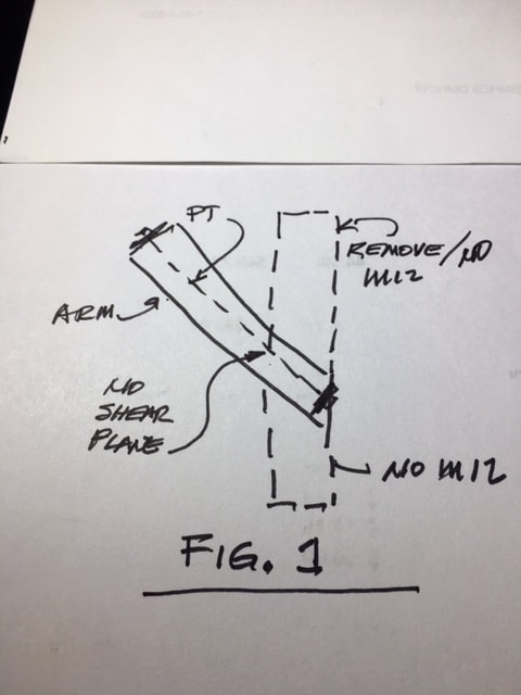
If we remove the parts of M12 beyond the projection of the Arm thru M12, your point becomes clear. I have attempted to show this in Fig 1.
FIU_M12_FIG_1_sc7wdf.jpg


But what happens if there is a severely sloping construction joint somewhere between the two PT anchors?
Or an identifiable plane which could simulate a joint. Perhaps this is a problem with concrete as a material and not something that can be applied universally to all materials.
Were M12 and the Arm cast while laying on their side and and monolithically, then forms stripped and allowed to cure and dry, it would likely crack at the interface with M12 due to shrinkage and drying stresses – concrete always seems to crack at reentrant corners.
Were the Arm cast alone and in one piece and then PT added, I see no reason for a diagonal crack to form so there is not a defined sloping plane for failure. Joining another and different section of concrete may create an opportunity for cracking and may define a plane for consideration. Casting M12 at a different time than casting the Arm clearly creates a joint and a defined plane.
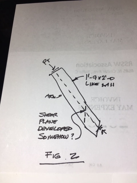
So IF, and it is an “if”, the Arm develops a defined sloping plane, the plane must transfer a component which creates shear at the plane. I tried to show this in Fig 2.
FIU_M12_FIG_2_jwgel7.jpg


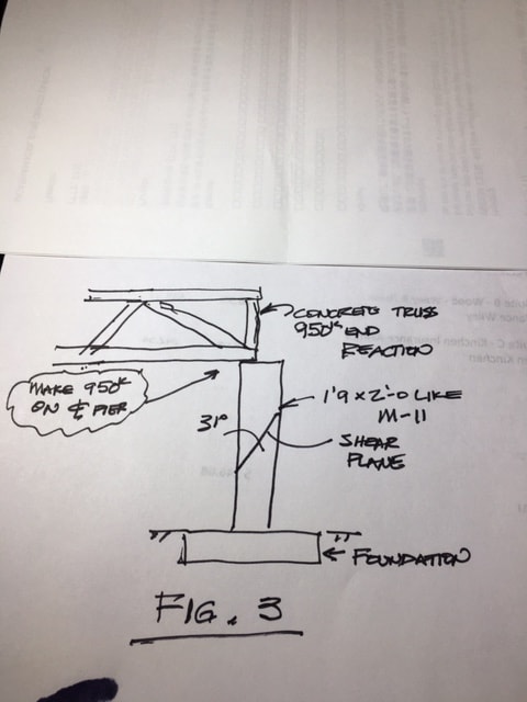
And I tried to illustrate my concern for not having significant axial load across a sloping joint in a compression member using Fig 3.
FIU_M12_FIG_3_swnl6f.jpg


No one would think of allowing a joint as shown in Fig 3.
Plus – if anyone had seen cracking in a pier at a sloping joint and that in anyway looked like the cracking seen on the deck at Node 11/12 they would have known it was coming down and soon. To see a 1'9” X 2 ft column (same size as M11) supporting one end of a 174 foot 950 ton concrete Albatruss (spelling intended) should have alerted someone. And M11 had much more load – about 1500 kips axial.
As I recall, the ACI code allowed or addressed Shear-Friction design where (paraphrasing here and not complete) different materials interface, where construction joints are used, and where a shear plane can be defined. I doubt that they ever envisioned a condition like M12 with a PT'd Arm.
OK, DDDDave – (note – my decoder ring is working again) now there are three sketches to admire. Better watch your six, Industrial Light and Magic.
Thanks,
 
saikee, I struggle with what it is that you can't see. WJE's imagination is also limited. The whole of your vertical plane CDEH has virtually no connective value, the result being that Member 12 becomes a vertical beam which 11 is pushing against. 12 is connected to the canopy on top and the diaphragm beneath the deck. There is no slice through 12 that sees the top of 12 move north while the bottom stays put. That is not a requirement for the collapse.

12 merely has to bow sufficiently for 11 to fail.

At the same time that the weight of the bridge is pushing moving out with 11, the slab is weighing down and pulling the diaphragm in the opposite direction. Neither force vector passes through the connection at the bottom of the diaphragm.

As waross suggests, the lower PT rod is likely the snag that prevented the bridge from meeting an earlier demise, an otherwise indeterminent structure bent on collapse.

The latest diagram that I posted, (and reposted by 3DDave) shows a movement by 11 of 1 inch, resulting in a rotation of 1.3 degrees. For ease of effort, the slab is held constant, and other fine detail of relative movements and deformations were omitted.

The point being that the movement is subtle but the damage to 11 at this point is already severe while the damage to 12 is not. It begs credulity that 12 would suddenly become the critical member.

Beyond this, at some point we just have to agree to disagree.

P.S. The various tears in the deck and spalls on the diaphragm are collateral damage and as such are distractions since these components are not critical elements.
 
Vance Wiley (Structural)

Thanks for your illustration. The sliding joint, as per 11/12 joint, will have shear across the CJ.

Can I have your thought on the action of 11 stressing and its structural duty? Both create comression inside the member and they are additive. I believe We all agree on that.

Would I be correct to say in prestressing Member 11 the 11/12 joint deflects to the South or towards the inner span?

When the bridge was droped on the piers by equilibrium the vertical compenent in Member 11 axial compression (plus self weight of Member 11) would be balanced by the vertical reaction from the pier while the horizontal comonent balanced by the tension in the deck. Member 11 had to act as almost like an arch but the 11/12 joint stoped it from kicking out so its deflection is to the North or away from the span.

Can Member 11 under two compressive cases deflect in opposite direction as I suggested above?

Also in the case of prestressing Member 11 do you expect the deck in compression, tension or no stress?


Paraphrase said:
While in the yard cracks were observed.
These cracks were superficial.
Coincidentally, these cracks later became the fracture plane.
Gibbs Rule #39: There is No Such Thing as Coincidence.
Gibbs Rule #51: Sometimes You're Wrong.

Bill
--------------------
"Why not the best?"
Jimmy Carter
 
saikee119 (Structural)6 Jul 20 20:07 said:
The only thing you need to watch out in WJE's work, as it was used to fend FIGG, is the assumed cracked line marked in yellow. That we can agree or disagree. The rest is as per documented photos so should be credible.
I'm sorry but "we" don't all see the photos showing any Testing of the deck as related to member 11. Testing member 11 as if it extended to infinity, does not address the complexity of the spaghetti blow of rebar, PVC pipe, hoses or cords, flex blue tube, etc. that visibly contribute to the failure. The diaphragm was cracked before the re-tensioning.

SF Charlie
Eng-Tips.com Forum Policies
 
SFCharlie's (Computer)

OSHA, NTSB and FIGG all offered reports on the FIU bridge collapse. The FIGG enclosed a report by WJE, a factual report by Turner Fiarbank Highway Resrach Centre and the NTSB Material Laboratory Study Report.

You can get a good idea how each describes the failure mechanism.

Like I said earlier WJE report was used to defend FIGG but the sketches, with the exception marked yellow lines stated as estimated cracks, were the crack mappings verifiable by the photos. WJE also show, via Exhibit 2.5.2 to 2.5.4 the broken out sections of 11/12 after the collpase. These are useful observed evidence, which are verifiable. to help our discussions here.

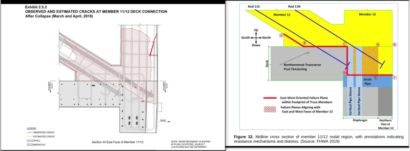
I would also point out the failure surfaces/planes between NTSB and WJE are substantially the same. In WJE case failure line between C-D-E is a striaght line instead of two sides of a right-angle triangle shown below.

comparison_of_NTSB_and_WJE_failure_surfaces_pj8nrn.png


I have intervened frequently because many discussions were not related to what had happen in the field.
 
waross (Electrical) & Sym P. le (Mechanical)

After both of you insisted on that the PT rods could have acted as "pins" or "snags" I take another look at the PT rods and rebars in Member 12.

The two PT rods are 1.75" diameter enclosed inside plastic ducts which I estimated to be either 3" or 4". By comparing with the exposed 4" verical sleeves in the phoros the duct is more likely to be 4" overall but it has ribs making the inside diameter smaller. In any case the point is there is free movement inside the duct for which I previously discounted its pining effect.

The vertical reinforcement inside Member 12 that pass through the CJ are 2x#11 (11/8" diameter) and 8x#7 (7/8" diameter). The combined steel area of these reinforcment is 1.6 times more than the 2 PT rod. These reinforcing bars were cast tight inside the concrete so would have to be in play immediately when 11/12 commenced shearing horizontally relative to the deck.

I don't know how much the PT rod play in resisting shear but it has a much yield strength of 120ksi against the rebar's 60 ksi so probaly a corresponding higher shear strength. The only problem is to realize the pin effect the 11/12 must deflect to take up the free slack isnide the duct.

Since the two PT rods, just like all the vertical rebar inside 12, did not sever so there exists the possibility their shearing capacity could have helped to restrain 11/12 joint from failure at least initially.
 
Sorry Vance - I specified they be traced over the existing design. ILM won't be returning your calls.
 
saikee119 (Structural)7 Jul 20 16:24 First, you have my upmost utmost respect. Second, it is my observation that WJE didn't include all the voids (conduits, etc.) that were in member 11. I think they decided what to look for and then created a test to find that (and nothing else). ...just my opinion, more based on my experience with human nature rather than structural engineering.

SF Charlie
Eng-Tips.com Forum Policies
 
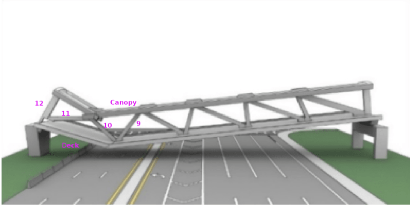
I am making one more attempt to sell my interpretation of the collapse sequence as it may help to reduce confusion. It was recorded on video that during collapse hinges were formed at 9/10/deck and 10/11/canopy as indicated below.
Full_bridge_model_annotated_l25hmt.png


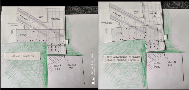
No. 1 is the condition before the collpase. No. 2 is the commencement of the collapse.
[Apology: I posted the unannotated sketches by mistake. The Editor does not permit me to change or replace the sketches so please read them in the order they appear]
c1_bjk9nn.png


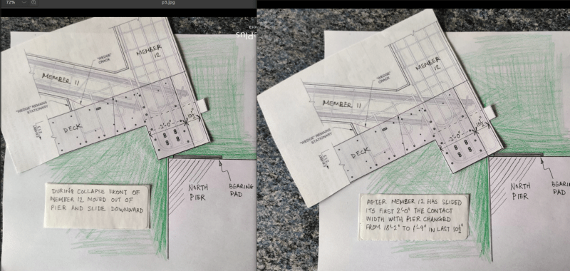
Since the bridge became a "V" shape it had to pull the two extreme ends inward. Thus allowing the diaphragm to move over the edge of the pier as shown by No. 3 & 4.
c2_mgzwwt.png


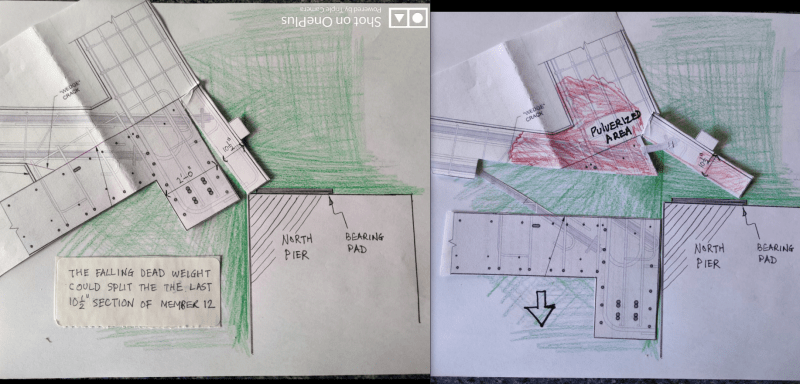
The diagragm is 18'-2" long for the first 2'-0" width. Thereafter the length drops to 1'-9", which is the thickness of Member 12, for the remaining 10.5" width. Based on the post collapse evidence it is likely that the deck fell to the ground once it had clear the pier edge. The caught last 10.5" width was split and broken up as indicated by No 5 & 6. sketches.
c3_fejdyp.png


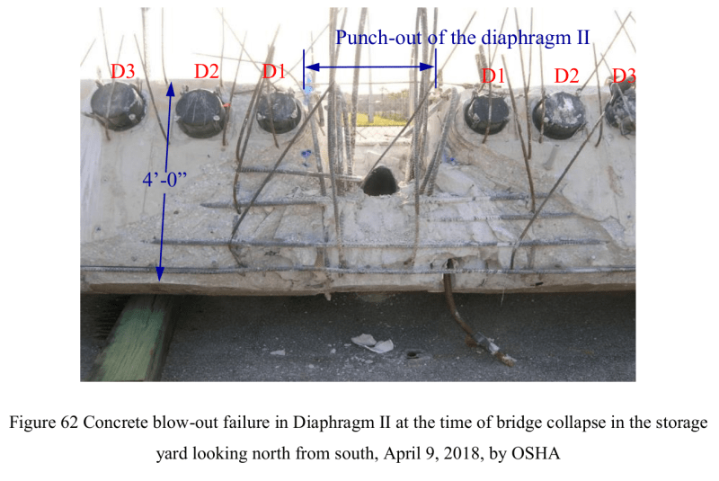
OSHA Fig 62 shows the sepration of the 1'-9" by 10.5" section managed to remove part of the surface layer of the diaphragm exposing some of the horizontal rebar at the north face.
F62_ipptvh.png

(by the way if you wonder what is the steel bar at the bottom of the diaphragm under the right D1 my guess is it could be a holding down bolt trapped inside the 4" vertical sleeve)

My interpretation may not the actual event but it is based on photographic evidence. If the part of Member 12 did split as suggested above the concrete would pulverize at the bottom anchor of the upper PT rod due a sudden to release of the high energy stored in the rod. The remain of Member 12 can be seen from the photo I posted in 5 Jul 20 11:52 post. Detail description of its interface plus off-site photos are also available in Exhibit B TFHRC Factual Report "Concrete Interface Under Member 11 and 12" of the FIGG Report.
 
There are hinge failures in the decks but those are secondary. You can't get a hinge failure in the decks until the much stiffer "truss" starts fail in some manner (unless there a localized hinge due to the spanning of the deck between joints which is not the case here). You also need a high force to pulverize the concrete. As soon as you have another failure mechanism (other than the shear friction/punch and pulverize mechanism), most of the load on #11 is relieved and you don't have the force to pulverize the concrete at the lower #11 joint.

The secondary hinge locations as seen on the video are as expected for a shear friction failure of #11 (or any other failure that would relieve load on #11).
 
Status
Not open for further replies.

Part and Inventory Search

Sponsor

Back
Top