Continue to Site

Eng-Tips is the largest engineering community on the Internet

Intelligent Work Forums for Engineering Professionals

  • Congratulations KootK on being selected by the Eng-Tips community for having the most helpful posts in the forums last week. Way to Go!

Miami Pedestrian Bridge, Part XIV 78

Status
Not open for further replies.

JAE

Structural
Jun 27, 2000
15,451
A continuation of our discussion of this failure. Best to read the other threads first to avoid rehashing things already discussed.

Part I
thread815-436595

Part II
thread815-436699

Part III
thread815-436802

Part IV
thread815-436924

Part V
thread815-437029

Part VI
thread815-438451

Part VII
thread815-438966

Part VIII
thread815-440072

Part IX
thread815-451175

Part X
thread815-454618

Part XI
thread815-454998

Part XII
thread815-455746

Part XIII
thread815-457935


Replies continue below

Recommended for you

Vance Wiley (Structural) said:
I would grout the smooth PT rods to protect them and the concrete sections from the elements. And the PT code requires that tendons be grouted, of course. So grouting would express a semblance of conformity and care.

Must admit I am not up to date with various design code changes but conduits for post-tension tendons and rods were used to be designed either grouted and ungrouted.

It is possible for long term durability the tendons and rod should be protected against corrosion and it makes sense to have them surrounded and protected by grout.

However there can be occasions where design conditions mandate a change in the tendon or rod tension so leaving the system not grouted is the only way. Over 40 years ago I designed a 2m thick roof experimental hall to house a nuclea fusion JET device. I had to cast the roof in 1m wide beams. Each had to be cast with shear key abutting the other. Each beam was a standard reinforced concrete design in one direction. On completion the other direction was stressed together by PT rods to act as a monolithic slab. This arrangement is for the eventual decomissioning to allow the roof to be demolished in small pieces after it has been soaked with years of radiation. The building is still operational today and I do not think the design codes would or could dictate the grouting arrangement of every post tension tendon or rod.
 
Sorry for switching here.

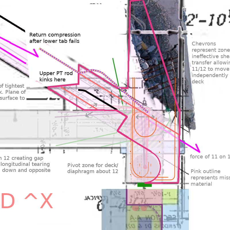
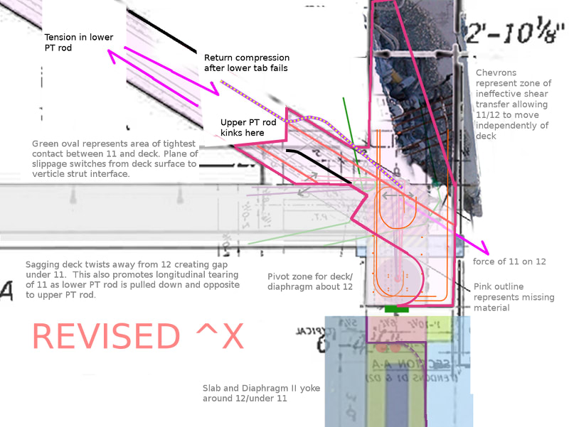
Consider the following as the explanation for the collapse sequence. It's about the split at the bottom of Member 11.

If the lower tab loses its integrity, the upper tab takes the load and kicks out. Member 11 pancakes guided by the lower PT rod. I still contend that the slab rotates the diaphragm off of the bottom of Member 12.

There is a plethora of cracking all throughout the 11/12/diaphragm from a variety of causes but none of those other causes advanced to the extent of collapsing the structure.

Deck_11_Overlays.2..13.plus.X.01_qmopuk.jpg


Deck_11_Overlays.2..13.plus.X.02_jzuuyt.jpg
 
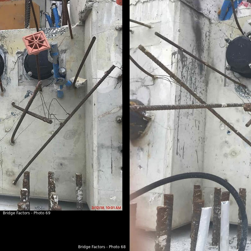
Two cracks of significance on the North portion of Member 12, one heavier than the other. The lighter one is at the level of the drain with a horizontal trajectory in keeping with saikee's failure plane.

The heavier one is above the drain and shows some displacement. It seems to follow the trajectory of the upper PT rod and would seem to align with cracking in Member 11.

Bridge_Factors_Photo_68_and_69_Column_12_Significant_Crack.4_vzihl7.jpg
 
I must learn to be a bit more specific.
Not sure what the last 15 years have brought, but 20 years ago it was required that PT be grouted in exposed structures and grouting was not required in protected structures, as in a structure with a roof membrane. That seems to make sense. As one architect loved to say "It seemed like a good idea at the time", I guess.
As a bit of history, one practice early in the use of PT in slabs, and from the period of paper wrapped strands to prevent bond and allow post tensioning after the concrete has cured, the system was touted as being waterproof if the compressive stresses were 300 psi or greater. The benefit was parking structures did not need a waterproof membrane, thereby avoiding the associated wear and repair.
Not the best idea - but it did provide a lot of opportunities for repair work. And the paper wrapping served well to maintain moisture in contact with the strands.
 
Sym P. le (Mechanical) said:
It's about the split at the bottom of Member 11.

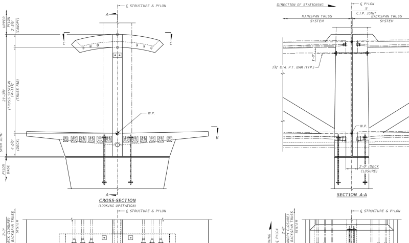
My interpretation of the spliting at bottom of Member 11 is a lot simpler than yours.
Bearing_point_tntpa6.png


Before the collapse the inner vertical face of the 2'-0" thick diaphram beam was flush with the inner face of the North pier. When the bridge started to fall it kinked at 9/10 with the deck and 10/11 with the canopy. Thus 9/10/deck and 10/11/canopy were two hinges and the bridge was no longer a structure but a mechanism.

The deck was well designed and didn't break into pieces but was virtual intact after the fall, right? So during the drop of 9/10/deck to the ground the deck's underside or more precisely the underside of 12 would have uplifted from the bearings and momentarily leaned against the southern edge of the North pier.

If the deck deformed to a "V" shape then the physical distance between the two extremities of the deck had to be shorten. This is just the property of a triangle that the sum of two sides is bigger than the third side. We now know at the Southern end the 1/2 of the bridge was resting on the Southern pier after the failure so if there were longitudinal shortening a relatively small amount would have taken place there. At the North end due to the "V" geometry and the underside of 12 was leaning against the edge of the pier there had to be a sliding action at the pier edge as a result from any reduction in the bridge's overall length. In fact the shortening was at least 2'-0" in order to enable the deck plus the diaphram beam to clear off the Northen pier.

Rather unfortunately Member 12 is 10.5" wider than the width of the diaphram beam so at the precise moment when the diaphram was able to clear the pier and commenced the drop Member 12 would be still caught up at top of the Northern pier because it still had 10.5" for sliding out. To me it was the dropping of the heavy deck that rip out the lower PT rod in Member 11 and assisted in further breaking out the 11/12 connection.
 
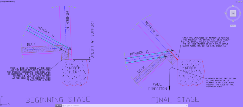
For some reason I can't edit my last post to add the following diagram so I have to post it in a separate thread.

Capture1_druxb9.png


At the beginning of the collapse the 11/12 support would move inwards due to 9/10 formed a hinge resulting the bridge deflected downards and shortened the span. This is indicated by the first sketch showing the diaphram started to lift off from the bearings. At some point the underside of diaphram would be able to lean against the southern edge of the northern pier. The motion from that point onward would be sliding.

When the bridge kept on deflecting there came a time when the diaphram could clear off the northern pier but the Member 12 couldn't because it has an extra 10.5" to go yet. At this moment the half span weight of the bridge would suddenly supported by the 21" wide Member 12 instead previously by the entire length of the diaphram which is 18'-2" long. The support length was abruptly reduced by a factor of 10. Thus Member 12 would split. The deck was able to drop freely down and rip out the lower PT rod in Member 11. I estimate the lower PT rod could have about 3" concrete from the external surface so it is easier to rip it out sideway than breaking in tension the 1.75" diameter PT rod.
 
saikee119 (Structural) 18 Jun 20 17:52 said:
Rather unfortunately Member 12 is 10.5" wider than the width of the diaphram beam so at the precise moment when the diaphram was able to clear the pier and commenced the drop Member 12 would be still caught up at top of the Northern pier because it still had 10.5" for sliding out. To me it was the dropping of the heavy deck that rip out the lower PT rod in Member 11 and assisted in further breaking out the 11/12 connection.

Refer to my "cut-and-paste mashup" in Part 12 - MikeW7 (Electrical) 22 Jul 19 03:24. It's crude, but the sequence of events seems to follow what was observed in the truck dash-cam video. Image 2 assumes the 11-12-canopy triangle remained relatively intact after the hinging began, in which case the canopy hinge combined with the rigid 12-canopy "L" section would have forced the 11-12 joint off the deck almost immediately and crushed the lower end of 11 in the pinch point where the lower end of 12 overhangs the deck end.

 
Refer to my "cut-and-paste mashup" in Part 12 - MikeW7 (Electrical) 22 Jul 19 03:24. said:
[/quote

Your "cut and paste" is pretty descriptive and definitely helpful. I think it needs a bit of scale, and removing M11 in pic 4 may be deceptive in the case of M12. Specifically, pic 4 shows M12 falling behind the pylon. That begs the question how did it climb back atop the pylon? I suggest M11 was still attached to the bottom of M12 and prevented M12 from dropping behind the pylon. There was 4 feet of the top of the pylon available to catch M12 before the deck started sliding south. This could explain some of the damage to M11 and the missing concrete from M11 and M12. It may also have contributed to the bend seen in the upper PT rod of M11. If the concrete near the base of M11 were damaged, either before initiation of collapse or during, and M12 were falling over the end of the deck or pylon with the lower anchor plate of the upper PT rod still embedded, the 35 kips or so DL in M12, supplemented by the force necessary to fail the canopy at Node 10/11, would bend the upper PT rod of M11, resulting in the bend seen in the upper PT rod in photos of M11 leaning on the pylon. There has been discussion of the upper PT rod being bent due to axial compression, but that seems unlikely to me because the upper end of the rod was free to move (it had just been tensioned for a second time) and the rod was not grouted so was not bonded.
The scale of pic 4 shows the structure having dropped maybe 20 feet (top of truss about level with top of pylon) at Node 9/10 while Diaphragm 2 is still on the pylon. The spreadsheet posted here
shows the diaphragm likely slipped off the pylon when Node 9/10 dropped about 11 feet.
The comments of 22 Jul 19 20:46 seem to hold today.
The numbers show that as Node 10/11 passes what was the original elevation of the top of the deck , N10/11 has moved north about 1 foot and the geometry shows diagonal M11 to be about 5 feet longer than the length of the canopy from the top of M12 to Node 10/11. Thus the base of M12 can be pushed about 6 feet northward from its original position. Then as Node 10/11 continues to fall below the top of the pylon it is M11 that restrains M12 and/or drags the bottom of M12 to its final position. M11 experiences a bit of damage in doing so.
Thank you,
 
Vance Wiley (Structural) 19 Jun 20 18:26 said:
Specifically, pic 4 shows M12 falling behind the pylon. That begs the question how did it climb back atop the pylon?
NOTE: I'm using my YouTube video below because it doesn't add any interpolated frames - it's "slowed down" by adding multiple copies of each frame.
[ul]
[li]The truck dash-cam video clearly shows 12 starting to dropping behind the pier at about the 11 second mark when the deck hinge has fallen about 1/3 the way to the street.[/li]
[li]I can't surmise an exact description of what happened to the lower half of 11, but whatever remained of it was most likely crushed, in or before the deck-12 pinch point, as soon as member 12 slid off the deck.[/li]
[li]When the "falling man" is visible a couple of frames later the deck hinge has almost hit the street (maybe one foot of daylight is still visible) and the 12-canopy "L" has fallen so far the canopy hinge appears to be resting on the remains of 11. Also note at this time that the deck end appears to still be on the pier.[/li]
[li]As the north section collapses on impact with the street you can see the deck slide off the pier, the "elbow" of the "L" appears to rotate on top of the pier until 12 is level, then the canopy hinge drags the "L" to it's final resting position with the base of 12 on top of the pier.[/li]
[li]With the exception of the actual collapse of the north bridge section, these events are what I tried to show in my cut and paste diagrams. The diagrams aren't accurate to the millimeter, but they're "close enough" to understand the torturous journey of member 12 as shown in the dash-cam video.[/li]
[/ul]

NOTE: numerous small edits since I first posted this.

 
MikeW7 (Electrical),

Your postulation assumed the hinge at 9/10 formed first, secondly the 11/12/canopy remained relatively intact and thirdly the rigid canopy “L” would have forced 11/12 joint off the deck.

The weakness in the model are :-

(1) The collapse was initiated by the hinge at 9/100.
(2) There was no joint blowout or a need of it.
(3) The deck finally rest against the northern pier and not flatly on the ground. If this wasn’t the intention the model has no explanation how the deck ended as it did.
(4) The canopy “L” was rigid and able to forced 11/12 out of the deck.


Answer to (1) The design of the bridge resembles to an “I” beam with the canopy as the top flange (in compression) and the deck as the bottom flange (in tension). The diagonal members are the equivalent web. In performing this structural duty the bridge’s neutral axis, where the stress is zero, would be somewhere in the middle of it 18’ height. If for whatever reason the web fails, say by the deck could not hold Member 11/12 in position, the support of the whole bridge would passes to the 2’ thick deck as it is the only bit left resting on the two piers. The second moment of area, which is proportional to the cube of structure height, would then be drastically reduced. The height reduction from 18’ to 2’ would be accompanied by a shockingly high stress increase in the order of 729 times. Clearly the deck had no such resisting ability but to buckle or hinge. Thus between the hinge of the deck and a functional loss of the web the former is less likely. Additionally the whole deck has been uniformly reinforced and post-tensioned by tendons without one part made stronger than the other. If the deck structure fails it should be at the point of maximum bending moment near the mid span and not at the end span.

Answer to (2) It was OSHA who used blow-out 10 times in its report. The importance of a blow-out is that it is sudden and most probably the starting point of a major structural collapse. This blow-out occurred when 11/12 was detaching from the diaphragm.

Answer to (3) I have already explained with sketches how the deck dropped flat onto the ground with my post on 19 Jun 20 12:14. This ties in well with geometry computation mentioned in Vance Wiley (Structural)’s post on 19 Jun 20 18:26.

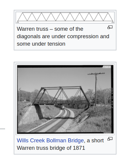
Answer to (4) Member 12 and the canopy are structurally superfluous to this bridge as it will stand if you chop them off and install the canopy post-tension anchors at the next bay. In fact a standard Warren truss does not have them. The easiest way to appreciate their insignificance is at each node the member forces must hold each other in equilibrium. At the top of 12 there was no opposing member. Neither there was any member on the other side of the canopy to balance whatever axial force inside the canopy. Therefore these two members have no significant internal forces. Structurally top of 12 has to support a portion of the canopy’s dead weight while the canopy provides anchorage for the prestressing tendons, in additional to its function as a weather shield.
Warren_truss_seg3v2.png

The canopy “L” was NOT rigid enough to be able to dislodge 11/12 out of the deck.
 
saikee119 (Structural) said:
The canopy “L” was NOT rigid enough to be able to dislodge 11/12 out of the deck.
Member 12 had an interesting ride. From the spreadsheet posted just after your posting of the original "cut and paste" model, the geometry shows that , as the structure fell and rotated about the bearing pad on the south pier, the following happened:
The top of M12 was pushed north about 2 inches as Node 10/11 fell thru a straight line from the south bearing to the top of M12.
At the same time, as the deck failed in bending at Node 9/10 and dropped about the same amount, 3 feet, the top of the deck and diaphragm 2 rotated into the fall, translating the base of M12 south about (3' drop/40' bay*48" = ) 3.6 inches. So now M12 is leaning north 5.6 inches out of plumb while the deck is now sloping south and down 3 feet in 40 feet. That deck slope should indicate M12 would be moving south at the top 3/40 * 16 feet = 14.4 inches.
Rotations, strains, and moments in M12 at the top of the deck are now equivalent to the top of M12 being forced north 20 inches from its original relationship to the deck. The remains of M12 suggest a bending failure with tension on the south face at the bottom of M12. Until it failed, M12 was applying torque on the top corner of the "blow out" block. While M12 possessed stiffness due to its 34.5 inch dimension, it only lapped ontothe deck by 24".
What was the magnitude of that moment at the base of M12? I hope someone with access to some design aids or computer programs can tell us that. I suspect M12 failed early in the collapse, maybe before Node 10/11 dropped 3 feet. We can see some damage at the underside of the canopy and south face of M11 M12.
Also, the damage to M11, in viewing the dash cam video of the collapse in the excellent frame by frame video work ( the creator of which I cannot identify now after 15 minutes of searching so I might give proper credit) posted , I see what appears to be Member 11 folding toward the canopy as the structure drops maybe 10 feet or so. Did M11 fail at Node 10/11 early in the collapse?
Regarding the initial movements of M12, the numbers support the post by SFCharlie (Computer)8 Jul 19 02:15
and his comments on 3 frames from the dash cam "(continues as 12 appears to remain vertical)", "(continues as 12 appears to remain vertical)", and "(Finally 12 tips)".
He also noted an angle change between M10 and M11 early in the sequence.
Thank you,

 
[b said:
Brady Heywood[/b] "Look at the cracks in the photograph below, which was taken two days before the failure by MCM (at Member 2). Try convincing yourself it’s thinner than your nail and not of concern."]

Hard to watch him criticize FIGG for not checking their work while his work needs checking.
It is Member TWELVE.
Fortunately no one died from his work. And in this case he can make his own deadlines.
He does present it logically, as I see so far. Much more to read.
Edit: Thanks for the link.
 
Sorry, Vance, but Member 11 was the diagonal in question, and where the telltale crack appeared at the lower end.

The Heywood presentation does succinctly tell part of the story of the fatal problems with this structure, and why the road should have been closed.

Edit: On further examination, I see that you were referring to the reference to "Member 2" in that one photo. I am yet to figure our the perspective of that photo. Taken 2 days prior to the collapse? Hard to believe.
 
hokie66 (Structural)29 Jun 20 20:48 said:
I am yet to figure our the perspective of that photo.
The same three two blue flex tubes appear in
Sym P. le (Mechanical)17 Jun 20 18:10 said:
(bottom photo)
to the left (ultimately north) of the two white pipes that weakened the diaphragm twelve joint allowing the blowout, (edit) so I think it is a close in wide angle shot.
 

Can anyone provide a link to PART 1: BRADY HEYWOOD BLOG please?
I cannot find it in Part 2 nor their web page.
I would like to read it.
Thanks,

 
Some thoughts about PART 1: BRADY HEYWOOD BLOG
Well written and clearly presented.


I would have went directly to post tensioning here - I cannot think of one piece of reinforcing member in this structure that is primarily in direct tension as a working member and depends on normal reinforcing. As presented, this statement appears to describe the post tensioning as - "additional"?

He starts counting time from the first indication of a problem - the blowout, and makes this statement after the picture of the bridge hitting the roadway.
Now if memory serves me from my elementary physics over 60 years ago "d=1/2at^2".
In 429 milliseconds a dropped bowling ball will drop less than 3 feet. Have I lost it? Has something changed that I did not notice?
The structure is about 18 feet above the street. The bowling ball will need about 1.05 seconds to hit the street. I would suspect a bit longer for the structure, because some progressive nature exists and at least minimal ductility. Rotating about the south bearing, the center of the bridge would drop 3 feet in 429 ms, ane the north end would drop only 6 feet.
Help me here.

 
Status
Not open for further replies.

Part and Inventory Search

Sponsor