Navigation
Install the app
How to install the app on iOS
Follow along with the video below to see how to install our site as a web app on your home screen.
Note: This feature may not be available in some browsers.
More options
-
Congratulations waross on being selected by the Tek-Tips community for having the most helpful posts in the forums last week. Way to Go!
You are using an out of date browser. It may not display this or other websites correctly.
You should upgrade or use an alternative browser.
You should upgrade or use an alternative browser.
Multiple single segment with dynamic modifier
- Thread starter Wuzhee
- Start date
- Status
- Not open for further replies.
- Thread starter
- #3
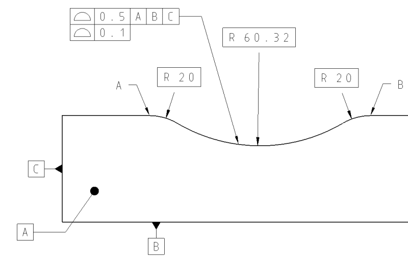
Sorry, forgot the A<->B between symbol.
There's no design behind this, I just made it up quickly. I'd like to understand how these two behave.
I have a previous thread where we discussed this but I did not want to bump that. My last interpretation of the partial sphere control got the interest of the design team and it looks like we will release that version.
Because the standard focuses more on those irregular shaped cutouts and overcomplicated revolutions I got headaches trying to uncover the definition that applies here.
Another vote for software that shows users compliant results for various callouts. This would eliminate the need to "uncover the definition" which is pretty straight-forward in the text of the document. It is unfortunate the writers ever used the term "size" in this regard, but that's why Y14.5 needs to be a picture book with no words of explanation.
- Thread starter
- #7
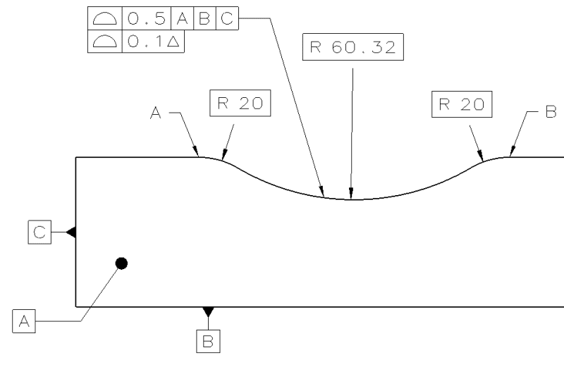
After a cup of coffee I read through the profile chapter of the standard and now it makes sense.Burunduk said:The dynamic profile tolerance modifier only makes sense for features of size.
Dynamic symbol gone, back to the upper drawing. Can the 0.1 wide lower segment progress inside the 0.5 wide zone in this case? (just like with dynamic in case of a FoS)
Picture book is for those who don't want to understand anything - they just copy and paste.
Software is for designers and engineers who want to understand how the callouts will function in production and inspection.
The clash is when copy-paste people demand that software won't work. Lots of conflict.
Software is for designers and engineers who want to understand how the callouts will function in production and inspection.
The clash is when copy-paste people demand that software won't work. Lots of conflict.
Whuzhee,
It will not act similarly to the dynamic profile. The tolerance zone is still distributed about the contour of basic radii, so it is bound to a certain curvature range limited within the 0.1 tolerance.
The meaning of no datum features referenced, is that the part is not constrained to anything during the evaluation of the lower segment/feature control frame, so a "best fit" to the tolerance zone is performed.
Burunduk said:The dynamic profile tolerance modifier only makes sense for features of size. Since the toleranced feature ("between" A and B, or if it was only the radius as well) is not a FOS, the meaning is not clear per the standard.
Burunduk,
Are you sure about that?
pmarc,
It is not explicitly stated that the dynamic profile is only applicable to features of size, but it is stated that "The function of the dynamic profile is to allow form to be controlled independent of size." And "size" being separated from the profile control is everywhere in the explanations wherever the modifier is mentioned.
So does this make sense for a feature without size? For me, it's more 'no' than 'yes'.
The examples are shown on irregular features of size (but obviously this alone does not rule out other cases, I mainly consider the text).
Someone may want to make an extension of the principle and say "hey, I apply it in this case to communicate that a radius is adjustable" (and not a diameter or the size of a closed shape is adjustable), but this can certainly be questioned.
Well, someone might say that the argument that the dynamic profile is applicable to features of size only doesn't defend itself in case of fig. 11-20.
I personally don't see a reason why it could not be applied in the example shown here and I am not sure I would even call it extension of principles.
I personally don't see a reason why it could not be applied in the example shown here and I am not sure I would even call it extension of principles.
pmarc
In fig 11-20 the dynamic profile is applied to a feature of size. An irregular one, but nevertheless a FOS.
On a different discussion someone stated: The function of the dynamic profile is to allow form to be controlled independent of size. The example given was the gas tank on a motorcycle, it is fairly easy to understand the form needs to be precisely controlled but the size can vary much more without detriment to function.
Pmarc,
Would you see a problem applying dynamic profile in fig 11-23/2018? A second segment to be added containing dynamic profile.
pmarc said:Well, someone might say that the argument that the dynamic profile is applicable to features of size only doesn't defend itself in case of fig. 11-20.
In fig 11-20 the dynamic profile is applied to a feature of size. An irregular one, but nevertheless a FOS.
And I agree with you assessment abovepmarc said:I personally don't see a reason why it could not be applied in the example shown here and I am not sure I would even call it extension of principles.
On a different discussion someone stated: The function of the dynamic profile is to allow form to be controlled independent of size. The example given was the gas tank on a motorcycle, it is fairly easy to understand the form needs to be precisely controlled but the size can vary much more without detriment to function.
Pmarc,
Would you see a problem applying dynamic profile in fig 11-23/2018? A second segment to be added containing dynamic profile.
pmarc said:...I am not sure everyone would agree that the cone is an irregular feature of size....
Everyone?? Not a realistic scope.
Well, agreement here on this forum or (just to expand a little bit) agreement in the real life with EVERYONE is not something we should shut for……Real life does not work like that
![[bigsmile]](/data/assets/smilies/bigsmile.gif "[bigsmile] [bigsmile]")
![[tongue]](/data/assets/smilies/tongue.gif "[tongue] [tongue]")
And thank you for confirmation about figure 11-23
pmarc,
The "means this" section of 11-20 states "the diameter of the surface shall be within the 0.2 profile of a surface tolerance".
With the idea of "FLOS" in mind, if the 0.02 dynamic profile controls "form, orientation and location", as stated, what is left for the 0.2 profile?
The implied answer may be controversial, but at least a cone is a special case and a gray area in which the term "size" has some meaning.
Burunduk,
I really don't want to start the conversation on cones again.
To me, much more important part is in trying to convince you and OP that the concept of dynamic profile tolerance zone may be quite easily applied to features that are commonly accepted as not being a FOS of any type, such as the arc feature shown in fig. 11-23 that greenimi brought up.
The unfortunate thing, in my opinion, is that in this context the interpretation of the term 'size' should be different than when used in the context of regular size limits but the committee wasn't able to find a better word to describe this geometric property, hence created confusion.
Do you see any valid reason for which the dynamic profile concept couldn't be applied in fig. 11-23?
"the committee wasn't able to find a better word to describe"
Understatement.
Which is weird as they make up definitions for other words. The math guys specify exactly what size means and the committee just wanders off to do their own thing.
There was no need to describe that factor at all but when there is a group project things can go sideways.
Understatement.
Which is weird as they make up definitions for other words. The math guys specify exactly what size means and the committee just wanders off to do their own thing.
There was no need to describe that factor at all but when there is a group project things can go sideways.
pmarc,
I do understand what you are getting at with figure 11-23 modified to include a profile segment with a dynamic modifier, but it is not that easy. There is also the form control aspect of the dynamic profile. The repeated emphasis in the descriptions of the dynamic modifier in the text of the standard is on the form control (being separate of size). Is curvature not a part of form? Clearly for cylindricity and circularity it isn't, but when a datumless profile is applied to a feature without opposed points which is dimensioned by a basic radius, don't we say that it controls the form? Similarly, a flatness tolerance - doesn't it keep a nominally flat surface from curving? So why a profile tolerance that doesn't prevent a nominally curved feature from straightening, by accommodating a possible increase in the actual radius towards infinity, be considered a valid form control?
I do understand what you are getting at with figure 11-23 modified to include a profile segment with a dynamic modifier, but it is not that easy. There is also the form control aspect of the dynamic profile. The repeated emphasis in the descriptions of the dynamic modifier in the text of the standard is on the form control (being separate of size). Is curvature not a part of form? Clearly for cylindricity and circularity it isn't, but when a datumless profile is applied to a feature without opposed points which is dimensioned by a basic radius, don't we say that it controls the form? Similarly, a flatness tolerance - doesn't it keep a nominally flat surface from curving? So why a profile tolerance that doesn't prevent a nominally curved feature from straightening, by accommodating a possible increase in the actual radius towards infinity, be considered a valid form control?
That is why you need an additional control to prevent the dynamic profile tolerance zone from becoming of infinitely large or small radius.
That is why on the OP's drawing the dynamic profile is merely a refinement and that is why greenimi suggested it to be a refinement of the existing profile requirement in fig 11-23.
As a stand-alone callout the dynamic profile would not fully control the features in both figures even if it was relative to a fully constrained DRF.
- Status
- Not open for further replies.
Similar threads
- Question
- Replies
- 7
- Views
- 57
- Locked
- Question
- Replies
- 17
- Views
- 48
- Locked
- Question
- Replies
- 7
- Views
- 15
- Locked
- Question
- Replies
- 7
- Views
- 16
- Locked
- Question
- Replies
- 1
- Views
- 9