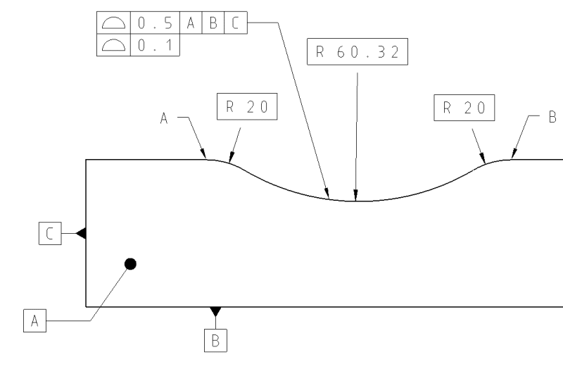
Eng-Tips is the largest engineering community on the Internet

Intelligent Work Forums for Engineering Professionals

  • Congratulations waross on being selected by the Tek-Tips community for having the most helpful posts in the forums last week. Way to Go!

Multiple single segment with dynamic modifier

Status
Not open for further replies.

Wuzhee

Automotive
Jul 12, 2022
269
0
0
DE
Hello,

This probably has been discussed before, but what's the difference between the two callouts below?

!EDIT! : profile applies between A <-> B. Forgot to add that under fcf.
MSS without datums
PROFILE1_gorv48.png

MSS with dynamic, w/o datums.
PROFILE2_tlf8ed.png
 
Replies continue below

Recommended for you

Burunduk said:
In the first example, basic ø3 defines the size of the cylinder, but not its location. The location of the cylinder is defined by 2.4 and 2.375.

In the second example dimensioned as in the second version by 2.4, 2.375 and R1.5, all three basic dimensions combine to define the arc's location relative to the origin of the datum reference frame, including the radius.

OK, in that case it seems like in your opinion the arrangement of basic dimensions does in fact matter. Interesting... So how would your interpretation work in MBD where basic dimensions are not shown on the face of the product definition but are queried from the CAD model? Or how would the dynamic profile wrt a fully constrained DRF work in case of the feature shown in fig. 11-24 in Y14.5-2018? Per my understanding of your interpretation, even though the feature is a closed contour, I suppose it wouldn't be able to work. Am I correct?


Burunduk said:
Here is a question - if a radius of 20° arc floats in space relative to its original placement but keeps its value (for example R1.5), do we say it dislocates/translates? I suppose the answer is yes.
If the same radius remains concentric to its original placement but changes the radius value (progresses) do we no longer say it dislocates/translates?

I will answer by just saying that I fully agree with Evan that it is not worth spending time on figuring out the meaning of all these different terms in cases like this. It's simply because in absence of clear and concise terminology in the standard for more complex scenarios, one term may mean different things to different people. All we need to know is the tolerance zone mechanics and its constraints to the datum reference frame, where applicable, and it can be worked from there for vast majority of real life scenarios.
 
Burunduk,
I just saw your second post with some additional sketches, however this doesn't change my answer to your question.
 
pmarc said:
OK, in that case it seems like in your opinion the arrangement of basic dimensions does in fact matter.

Not at all. It's the type of the feature/the geometry of the feature that makes the difference, not how the basic dimensions are given. However, I do find that different types of basic dimensions can define different properties of a feature. A diameter dimension does not define location unless it's for example a pitch diameter for a pattern of holes. The diameter of a cylinder does not define the location of that cylinder. A small angle arc can be located by its radius dimension when either the location reference is the center of the radius or another locating distance is given from a reference to the center of the arc's radius. A basic angle doesn't define the location of the inclined feature. A single linear distance to a point on a line depicting a planar surface doesn't define the orientation of the surface, and so on. Is all this meaningless just because one has different options to dimension the same geometry?
Locating dimensions are meaningful for controlling translational DOF. Orienting dimensions are meaningful for controlling rotational DOF. Size dimensions are meaningful for size controls.
On a CAD model, if I want to determine the location of a cylindrical feature, I won't be measuring the diameter for that purpose.

Figure 11-24 would work fine with a dynamic profile because as long as the centroid is kept in place, the shape can expand and contract without changing location.

pmarc said:
I will answer by just saying that I fully agree with Evan that it is not worth spending time on figuring out the meaning of all these different terms

And nevertheless, what does "translation" from the part of the definition that states "the tolerance zone is constrained in translation" mean to you in the context of a small angle arc? Or are you saying that we can ignore that part of the requirement because "translation" has no separate definition in the standard and "may mean different things to different people"?
 
Burunduk,
Thanks for the converstation. Your last reply indicates to me that I won't be able to convince you that the dynamic profile concept makes sense not only for closed contours. You seem to be standing hard on arguments that, in my opinion, are based on questionable ideas. Your answers to my questions about MBD and fig. 11-24 just reinforce this impression.

Perhaps someone else, maybe Evan, will have more luck.
 
pmarc,
That's a shame, because I was genuinely interested in your idea about what "constrained in translation" as defined in the standard (11.10.3) may mean in the context of a dynamic profile tolerance zone for a small angle arc.

I am left with only a guess that you might think of 'translation' as a term describing only the variation between the 2 arcs shown in right side of my recently posted sketch but not the left side. I truly think this is a key point worth addressing that actually could have changed my mind had you communicated your point of view on it in a way that supports your position, but from some reason you avoided it.
 
Burunduk and All,

Now this is getting interesting ;^).

I agree with pmarc that the arrangement of the basic dimensions (or complete lack thereof in the case of MBD) makes no difference to the definition for dynamic profile. So both versions of the drawing with the arc feature would work equally well and define the same dynamic profile requirement (as would an undimensioned drawing with CAD as basic).

Here are answers to the questions from the 12:57 post. If the arc floats in space but keeps the same radius, I would say that it has translated. If the arc keeps the same center but changes radius, it has progressed and not translated.

Here are some comments on the statements from your last post at 15:01. I would say that different types of dimensions can define different properties of a feature, but only in the context of directly toleranced dimensions. These different properties do not apply in the context of basic dimensions. So the question of which basic dimensions orient or locate a feature isn't really important and I'm not sure that there is even an answer to that.

In order to make sense of all of the different types of profile tolerance, I had to use a different paradigm. Instead of thinking of what variation types are controlled on the feature, I think of it in terms of the tolerance zone and what constraints and transformations it has. So it's a zone defined with offsets from the true profile, and then being allowed to translate, rotate, or progress. This sometimes has a simple connection to location-orientation-size-form, and sometimes it is not so simple. But the zone-based approach definitely makes mathematical definition much more straightforward.

Evan Janeshewski

Axymetrix Quality Engineering Inc.
 
Burunduk,

Another comment on the idea of translation, and what it means in the context of the dynamic profile definition. Here is how I see it. "Constrained in translation" means that the tolerance zone is not allowed to translate relative to the true profile. The dynamic modifier does not allow the tolerance zone to translate relative to the true profile - it allows it to progress relative to the true profile. This applies in the same way to a small angle arc as it does to a closed feature.

The lower segment of a composite profile tolerance allows the tolerance zone to translate relative to the true profile.

Evan Janeshewski

Axymetrix Quality Engineering Inc.
 
Evan said:
If the arc floats in space but keeps the same radius, I would say that it has translated. If the arc keeps the same center but changes radius, it has progressed and not translated

Is there a solid definition that supports that? Something in the new version of the math standard may be?

Does it mean that the variation between 2 arcs shown on the left side of the sketch from 13:57 is not limited/affected under the condition of the vertical translational degree of freedom being constrained?

It may be nice to describe everything with constraints and transformations on the tolerance zone, but since the requirement is eventually described with words, it is still necessary to say something definitive that will indicate that 'translation' is shown only on the right side of the 13:57 sketch.
 
Burunduk,
You hold very tightly to the terminology in this case. I didn't provide a direct answer to your question because even if I did, it wouldn't really matter much since the standard does not provide solid definitions for translation, dislocation, progression or what have you, and so that would just be my opinion. Instead, I (and Evan) recommended to rely on the relatively simple mechanism for the creation of the dynamic profile tolerance zone without having to go into the terminology weeds.

To give you an example of why we all should (unfortunately) be very careful with the terminology used in Y14.5 standard (especially in its 2018 version), I would offer the following example. Notice that it is pointing at an issue despite that explicit definitions exist in the standard, so it isn't even close to the level of ambiguity being discussed in this thread.

ASME Y14.5-2018 said:
3.32 FEATURE AXIS
feature axis: the axis of the unrelated AME of a feature.

3.33 FEATURE, CENTER PLANE OF
feature, center plane of: the center plane of the unrelated AME of a feature.
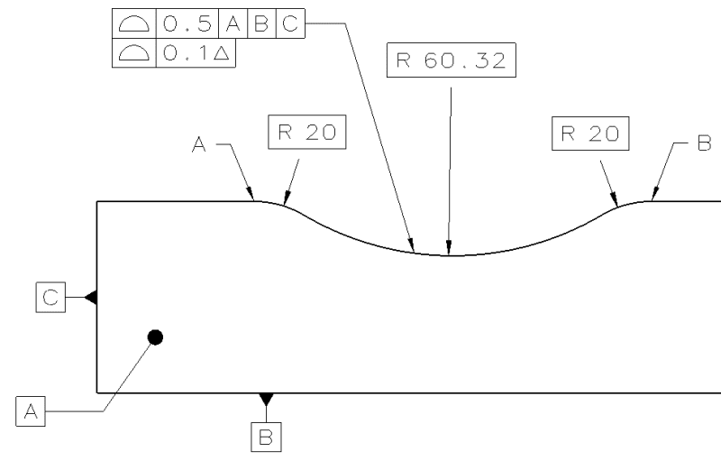

5.9.6 Effect of LMC
[...]
5.9.6.2 Explanation of the Axis Method. When an orientation or position tolerance is applied on an LMC basis, the feature’s axis, center plane, or center point shall not violate the tolerance zone. The tolerance available is the specified value if the unrelated actual minimum material envelope is at the LMC limit of size. When the size of the unrelated actual minimum material envelope of the feature departs from LMC, the tolerance zone increases. The increase in the tolerance zone is equal to the difference between the specified LMC limit of size and the unrelated actual minimum material envelope size. The resulting tolerance zone is equal to the stated geometric tolerance plus the additional tolerance. See Figures 10-15 and 10-17. The total permissible variation for the specified geometric characteristic is maximum when the unrelated actual minimum material envelope of the feature is at MMC, unless a maximum (“MAX”) is specified in the feature control frame.

So in the light of this, should we now understand that for the axis method of tolerances at LMC one must find the UAME axis or center plane as the feature that needs to fall inside the tolerance zone, but at the same one must calculate bonus tolerance based on the UAMME size?

Apologies for the offtop.
 
pmarc said:
So in the light of this, should we now understand that for the axis method of tolerances at LMC one must find the UAME axis or center plane as the feature that needs to fall inside the tolerance zone, but at the same one must calculate bonus tolerance based on the UAMME size?
Yes, this is exactly how I interpret the axis control definition of an LMC tolerance in Y14.5. If recall correctly, the corresponding definition in the new Y14.45 standard on measurement data reporting is different because the "measured" versions of the feature axis and feature center plane changed relative to Y14.5 to be able to be produced from the "minimum material" envelopes for LMC-modified tolerances, so that the controlled element and the size considered for the bonus tolerance are to be determined from the same envelope depending on the material condition in which the tolerance applies. This is nice and makes sense functionally, but now there is a discrepancy between the standards. I could understand the logic of sticking with just the Unrelated AME, had the size used for the bonus calculation also been determined from it. It could allow inspection with pin gages. But I do understand your warning from relying on terminology too much.

pmarc said:
You hold very tightly to the terminology in this case.
I look for the answers in the terminology in the text, because it is counterintuitive for me that a feature of size (closed shape) and a feature without opposed points are treated the same when it comes to the expectation from the tolerance zone to "progress" per the dynamic profile concept. Why counterintuitive? Look again in my last sketch. If the R1.5 arc on the top of both the left side and the right side is the 'before' version, then what should make me think that the process that caused the 'after' result should be called 'translation' on the right side, and on the left side 'translation' did not occur? It makes more sense that if both arcs shifted in the negative direction of the vertical axis, they both utilized a translational degree of freedom, in other words they both translated, even if in one case the arc remained concentric to its original version and changed its radius value, and in the other case it remained with fixed curvature and simply moved as it is.

3DDave said:
how do you define the word "translation" in the context of geometric discussions?
In simple words, translation in geometry is when some geometric element moves from one place to another. You can detect it by the change in linear distance from a known reference. In tolerancing, the term is related to variation in location.
 
Thanks for Googling that answer for me.

It appears to answer your previous question about translation concerning a solid definition.

 
Burunduk,

I'm not sure that I'll be able to explain the tolerance zone translation and progression concepts in the context of your example with the 1.5 arcs. We can look at the same piece of geometry and say either "it progressed" or "it changed shape and then translated" or "it translated and then changed shape". I suppose that my point is that the progression concept ends up being a simpler way to describe what happens in a variety of cases.

Here's an example in another context. Total Runout can be applied to various different surfaces of revolution - cylinders and planar surfaces are the most common. Cones and curved surfaces are less common but possible. For a cylindrical feature, there is a tube-shaped zone that can grow or shrink while maintaining the same "wall thickness". For a planar feature, there is a parallel-plane zone that is often described as translating along the datum axis. For a conical or curved feature, it's much more difficult to describe. What happens to the zone is a combination of growing/shrinking and translating. Anyway, what happens for each of these feature types is a manifestation of the FIM concept - full indicator movement as we sweep the indicator along the basic contour. In terms of a tolerance zone, FIM correlates to progression of the zone. What it looks like depends on the feature type. For cylinders, progression looks the same as the diameter of the zone growing or shrinking. For the planar surface, progression looks the same as translation. For the cone or curved surface, progression looks like an odd mixture of both. So again we can look at the same tolerance zones for a cylinder and a plane and say either "the zones progresses in both cases" or "in this case the zone grows, and in that case it translates".

I suppose that which description is simpler would mean different things to different people.

Evan Janeshewski

Axymetrix Quality Engineering Inc.
 
3DDave said:
Thanks for Googling that answer for me.

It appears to answer your previous question about translation concerning a solid definition.

The definition I gave you is not from Google. I did not ask for a solid definition, I was saying that the requirement of being constrained in translation should not be ignored. It should be carefully considered in the context of dynamic profiles of unopposed features because the expected "progression" which makes the tolerance zone dynamic is tightly related to the ability to translate (even if not the same way as in "pure" translation).

Evan said:
I suppose that my point is that the progression concept ends up being a simpler way to describe what happens in a variety of cases.
Progression for a small angle arc can be viewed as a combination of translation and deformation (change of curvature).
My point is that if "progression" in the case of a regular profile with datum references is limited by a constrained translational degree of freedom just like simple translation is, there is no reason why it should be interpreted differently for the dynamic profile. With closed shapes it is different because the tolerance zone as a whole doesn't move from one place to another, so it's not comparable to translation. This is the difference I was talking about.
 
You literally asked for a solid definition, but maybe you didn't phrase the question precisely enough to convey whatever you thought you were asking.

Translation is a special case transformation where each element is transformed by addition of an identical vector. For every point on the original geometry there is a matching point with the same vector offset. It's not "when some geometric element moves from one place to another," which also describes scaling, rotation, and projection.

Everything in engineering is to be carefully considered, particularly understanding the mathematics of general geometry transforms. There are some excellent references online.

It's not different for closed shapes. Just because "progression" can look like translation doesn't mean it is translation.

offset_dmgknb.png


One can see the mathematical description matches this:

"When the dynamic profile tolerance modifier is applied, the zone is permitted to progress (expand or contract normal to the true profile) while maintaining the specified constant width (distance between the boundaries)."

The effect is this:
offset2_gtkcdf.png


No opposition involved or required. It does hint at problems the committee ignores just the same as for profile crossing any sharp corner - that there are portions that are effectively absorbed or extrapolated and it might eliminate small segments entirely or invert connections.
 
3DDave,
The exactly same concept of progression as you showed in your last graphic is applicable to a planar surface.
Can a planar surface progress if it is constrained in translation? If the answer is no, then the effect of progression is shape dependent - as I was saying all along.
Progression for a planar surface is dislocation, and it is limited by a constrained translational degree of freedom. Progression for closed surface results only in change of size. Progression for a small angle arc is more like the planar surface case than like the closed surface, and is also affected by availability of translational degrees of freedom.
 
Evan, pmarc, and all
Here is a clarification of where the problem is.

As you may remember, I was addressing the multiple single segment case with the dynamic modifier, which in my opinion cannot be applied the same way for opposed and non-opposed features.

ASME Y14.5-2018 said:
When the dynamic profile tolerance modifier is applied in a segment of multiple single-segment feature control frames and includes datum feature references, the tolerance zone is constrained in translation and rotation, but not size, as applicable

arc_transformations_vs_closed_shape_pezzf3.png


The continuous lines in the 3 cases represent the default position of a true profile, and the coordinate system represents the datum reference frame origin. The dashed lines represent the true profiles after a transformation. In case 1, progression occurred, but the true profile as a whole stayed in a static location relative to the datum reference frame, so the condition of being constrained in translation is met.
In contrast, in cases 2 and 3 the true profile has shifted in the negative Y direction relative to the DRF origin; the overall distance from the origin to the true profile decreased. This means that there could not be an active translational constraint in this direction.
Case 2 is a simple translation, while case 3 is progression per the dynamic profile definition. Contrary to case 1, case 3 cannot take place with a datum reference that constrains Y. This, in my opinion, makes dynamic profile per sub-paragraph 11.10.3 inapplicable to a non-opposed feature.
 
Let me ask another question which got my attention.
ASME Y14.5-2018 said:
10.5.2 Multiple Single-Segment Positional Tolerancing
"The datum feature references in any segment are not permitted to be an exact repeat of all the datum feature references in other segments. Each complete horizontal segment may be verified separately."

ASME Y14.5-2018 said:
11.7 MULTIPLE SINGLE-SEGMENT PROFILE TOLERANCING
For multiple single-segment profile tolerancing, datum feature references are interpreted the same as for multiple single-segment positional tolerancing. See para. 10.5.2.

If profile is interpreted the same as position, how can for example Figure 11-20 comply with the wording? The bottom row datum references are an exact copy of the top row. Which is forbidden by 11.7.
If I can't do it in case of position, why can they do it with profile? Only because the dynamic modifier? Or because it's a cylindrical body and doesn't have all 6 DOF locked?

 
And to further add to my confusion:
ASME Y14.5-2018 10.5.2 said:
Each complete horizontal segment may be verified separately

Example:
PROF1_uorbzs.png

If each row can be verified separately, then lets say I measure the upper row first. I put my part on the table, get a height gauge and verify the 92,42. It must lay inside the 6 wide zone.
Secondly I verify the lower bracket which is my "form refinement".
Even if I do it reverse order, the end result is the same. The height can be 90 mm and have a flatness of 1 mm, or 94mm and a flatness of 1 mm. Either way the 1 mm tolerance zone "progresses inside" the 6 mm zone. Or whichever combination that lays inside both tolerances.
 
Wuhzee, for your first question about paragraph 10.5.2 versus 11.7, there does seem to be an inconsistency. Figure 11-20 is fine because of the dynamic profile modifier. If you compare the same paragraphs in 2009 (7.5.2 vs. 8.7) they have the same statement, but the dynamic profile modifier didn't exist then. So I think they goofed and forget to tweak that rule when the dynamic modifier was introduced in 2018.

For your second post about verifying the two segments separately, their statement in 10.5.2 didn't imply a chronological order for which gets measured first (upper or lower segment). They just meant that each segment is verified without maintaining the requirements or constraints of the other segment.
 
Status
Not open for further replies.
Back
Top