Eng-Tips is the largest engineering community on the Internet

Intelligent Work Forums for Engineering Professionals

  • Congratulations waross on being selected by the Tek-Tips community for having the most helpful posts in the forums last week. Way to Go!

Multiple single segment with dynamic modifier

Status
Not open for further replies.

Wuzhee

Automotive
Jul 12, 2022
269
0
0
DE
Hello,

This probably has been discussed before, but what's the difference between the two callouts below?

!EDIT! : profile applies between A <-> B. Forgot to add that under fcf.
MSS without datums
PROFILE1_gorv48.png

MSS with dynamic, w/o datums.
PROFILE2_tlf8ed.png
 
Replies continue below

Recommended for you

Garland23 said:
They just meant that each segment is verified without maintaining the requirements or constraints of the other segment.

Yes, and this is why I first asked if they're different, because if I were to measure that L shaped part in my example, I'd put it on a CMM table, measure the flatness of the top surface (the 1 mm profile tol.) then I'd measure the height. Software can detect if the surface is out of boundary, then it can validate the height. Or in the case of no modifier, the 6 mm wide zone is overly generous and unnecessary? Because the lower segment "overwrites" the upper?

I really don't see the thing with the dynamic symbol. Single profile controls work fine most of the time without trouble. If I were to further refine the LOF of a surface, I'd just slap a bottom row with a tighter tolerance then call it a day. No need for fancy symbols. But now we must use the symbol to clearly state that we're unlocking the "size" aspect of tolerancing. [sub](The only thing missing is CATIA lacks the symbol (and many more) but that's off the topic...)[/sub]
 
Wuzhee,

I agree with Garland23. The statement in 10.5.2 needs to be updated - good catch.

Regarding the drawing with two single-segment profile tolerances, there is an issue with the specification. The lower segment does essentially the same thing as the upper segment, only with a smaller tolerance. The second callout is not just a form refinement - it references A|B| and thus controls the orientation and location relative to both A and B. The toleranced feature is perpendicular to datum feature C, so referencing C doesn't provide any additional control.

If this was a composite profile feature control frame instead of two single segments, then the lower segment would be a refinement of form and orientation, and not control the distance from datum A.

Evan Janeshewski

Axymetrix Quality Engineering Inc.
 
Evan said:
The second callout is not just a form refinement - it references A|B| and thus controls the orientation and location relative to both A and B.

This is really the only sensible way to explain such things. If instead of using the terms form, location and orientation you tried to explain this with constraints and transformations on the tolerance zone, I think this would be much more difficult for you and for whoever needs the explanation, wouldn't it? I think that these are important terms that can and should be used without ambiguity. These 3 and 'size' shouldn't be ignored whenever mentioned in the standard.
 
Burunduk,

There are a couple of things that seem to be the sticking points here.

One detail is that the true profile does not progress - it's the tolerance zone that progresses. So there is no issue with overriding the basic geometry from the drawing or model, because that just defines the true profile. The dynamic profile tolerance zone "starts off" as centered on the true profile, and then is allowed to progress away from it. Here is how it would apply on your part with the arc surface:

ArcSurfProgressedZone_szzlw7.png


The dyhamic profile zone (green) has progressed away from the basic surface (black). I literally used the CAD function called Offset to create the boundaries - the Move function would have translated them ;^). Even though we could describe the final result as a combination of translation and shape change, that's not what the transformation was. The zone is still constrained in translation, because we haven't allowed it to translate.

Evan Janeshewski

Axymetrix Quality Engineering Inc.
 
Burunduk said:
Yes, this is exactly how I interpret the axis control definition of an LMC tolerance in Y14.5. If recall correctly, the corresponding definition in the new Y14.45 standard on measurement data reporting is different because the "measured" versions of the feature axis and feature center plane changed relative to Y14.5 to be able to be produced from the "minimum material" envelopes for LMC-modified tolerances, so that the controlled element and the size considered for the bonus tolerance are to be determined from the same envelope depending on the material condition in which the tolerance applies. This is nice and makes sense functionally, but now there is a discrepancy between the standards. I could understand the logic of sticking with just the Unrelated AME, had the size used for the bonus calculation also been determined from it. It could allow inspection with pin gages. But I do understand your warning from relying on terminology too much.

As this is an offtop, I will keep it short. Unfortunately, this is not how it should be interpreted. Y14.45 merely mimics para. 7.2.2 in Y14.5.1-2019.
 
Burunduk,

I would say that there are a lot of situations where the form-size-orientation-location description is adequate, and some where it is not.

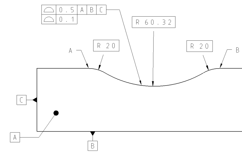
My explanation of the lower callout above was actually somewhat oversimplified - it glossed over several things. Even for a relatively simple part, the F-S-O-L breakdown can become complicated. Here is a statement from Section 11.2 in Y14.5-2018:

"Profile tolerances are used to define a tolerance zone to control form or combinations of size, form, orientation, and location of a feature(s) relative to a true profile."

The lower callout controls a combination of size, form, orientation, and location. Here's an admittedly somewhat exaggerated, but still realistic, discussion of how these things would apply to the lower callout:

Size: Profile can control size, but it doesn't in this case because the toleranced feature is a planar surface so it doesn't have size. On the other hand, the distance between the toleranced feature and datum feature A (the height) could have been controlled with a size tolerance. Does that mean that the profile tolerance is controlling size in some way?

Form: The form characteristic applicable to the toleranced feature is flatness. It would have to be flat within 1 in order to conform to the profile tolerance, so form is being controlled. This is relatively straightforward.

Orientation: The toleranced feature is nominally perpendicular to datum feature A. It could only be tilted by 1 mm relative to A and still conform to the profile zone, so orientation to A is being controlled. The toleranced surface is nominally parallel to datum feature B, so it could only be tilted by 1 mm relative to B and still conform to the profile zone - well, wait a minute. The zone is only aligned parallel to B in one sense, because A is primary. So the toleranced surface is oriented to A in one sense and oriented to B in the other.

Location: Profile can control location, but the toleranced surface cannot be located to A in this case because it is nominally perpendicular. The profile zone controls the location relative to B, but it's not the same thing as the distance from B because A is primary.

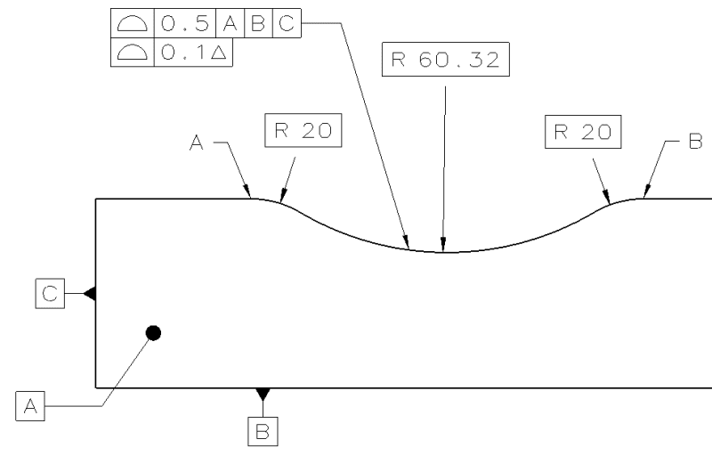
Now here's an attempt at the non-sensible constraint-based description:

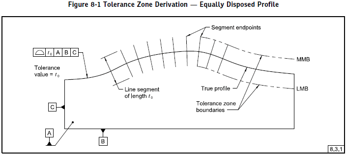
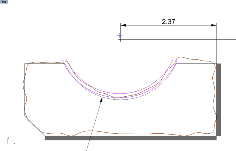
The profile zone is two boundaries 1 mm apart that are equally disposed about the true profile. By default, a profile zone has no transformations relative to the true profile. The true profile has a basic relationship to the true geometric counterparts for datum features A and B. The datum features of the actual part must have full contact with those counterparts, in the order specified. This allows us to derive the result:

Profile_AB_for_Eng-Tips_Post_March_6_tpyico.png


I find the constraint-based description easier to understand, even for a relatively simple case like this one - your mileage may vary. However, I would also say that the constraint-based description is much easier for tougher cases like the unopposed surface with dynamic profile.

Evan Janeshewski

Axymetrix Quality Engineering Inc.
 
Evan said:
One detail is that the true profile does not progress - it's the tolerance zone that progresses
That's true. I was kind of stuck with the idea that a bilateral equally disposed tolerance zone is always centered to a true profile, and so I imagined that if the tolerance zone expands or contracts it accompanies the same behavior of the true profile. It saved me the effort of making a few more circles and arcs in the sketches, but I ended up with an example that doesn't describe the problem accurately enough. Still, it doesn't change the substance of the point being discussed because the requirement of constrained location applies to the tolerance zone, and so if each curve is thought of two parallel curves, the example is still good at showing what I think to be the principally different results of applying the dynamic profile to the 2 types of features. The parallel arcs zone has shifted in location, while the coaxial cylinders zone did not. If the arcs didn't shift in location, does it mean that any element of circular shape, regardless of what portion of a 360° circle it constitutes, can only be located by the center of its radius?

Evan said:
The zone is still constrained in translation, because we haven't allowed it to translate
Would the same be true if the toleranced feature was a planar feature instead of an arc, and the dynamic tolerance zone was progressing?

Evan said:
The lower callout controls a combination of size, form, orientation, and location.
I only see how it controls form, orientation and location like you initially said. It doesn't really control size because it can only limit the maximum value up to a maximum of 92.42+1/2=92.92 per the basic dimension from datum B and the profile tolerance value. But it doesn't control the minimum limit of size because the minimum surface-to-surface distance between the toleranced feature and datum feature B would depend on the form and orientation (relative to datum A) controls applied to datum feature B (not shown). So it is outside the scope of that 1 mm profile tolerance with ref. to datum features A and B. Controlling just one limit is not a size control. Do or do not. There is no try.
 
Any point along the circle has a place the normal vector points at - the new point is in a different location. That there is some average behavior is immaterial.

For each point on the true surface create a vector normal to that surface at that point that controls the progression and another along that vector that represents the width of the zone at the tip of those vector normals, then let all the surface normal vectors change magnitude (not direction) simultaneously. If the as-manufactured surface at the intersects all the width normals at some magnitude of the vector normals, then the surface of the as-manufactured surface is conformant to that requirement.

 
3DDave,

Thanks for the background material on translation. We didn't provide a definition for the term "translation" in Y14.5.1, but the way that it is used is nothing out of the ordinary as far as I know. It's one of the fundamental affine transformations.

Your vector-based definition for the dynamic profile requirement is interesting, very 14.5.1-ish. The profile zone was defined as the locus of line segments that are normal to the true profile:

Figure_8-1_from_51_zvy2rp.png


The dynamic profile zone definition will likely be an extension of this, I'm not sure yet.


Evan Janeshewski

Axymetrix Quality Engineering Inc.
 
Burunduk,

We may have to eventually agree to disagree on this. If we take a short segment of the arc-shaped zone and perform a geometric operation on it, I don't think that the the presence or absence of an opposed portion of zone would change the operation that was performed. I'm not sure that my next comments are going to be any more convincing - especially when we get to the planar surface case ;^).

I'll try to address the questions asked in your last post:

I don't think it means that any element of a circular shape, regardless of what portion of a 360° circle it constitutes, can only be located by the center of its radius. An element of a circle is a special case in that it even has a unique well-defined center. We need to be able to locate shapes that do not have a center (like the irregular feature in Figure 8-19). There is no well-defined center geometry of that shape. You could calculate a centroid, but I don't know if that point would stay constant as the surface progressed. The feature is located (that is, its location is controlled) in the PLTZF due to the fact that we don't allow the zone to translate away from the true profile. It doesn't need to involve a center.

This is what it would look like if we allowed the zone to translate. I've left in the center point to show how far it moved, but we don't really need that.

ArcSurfTranslatedZone_xdf9ak.png


This zone is what we would result from a composite profile FRTZF (lower segment) that referenced A. The zone is allowed to translate relative to the true profile, but is not allowed to rotate or progress. This is how we defined the action of the FRTZF in Y14.5.1-2019.

If we applied dynamic profile to a planar surface, I would still say that the zone is constrained in location because we haven't allowed it to translate. I know that this will be even more difficult to accept ;^). But I would also say that the end result of progression in this special case is identical to the end result of translation. So applying dynamic profile to a planar surface can get the same final result as applying a composite profile FRTZF. I'll add this to the diagrams if I have time.

There is even some other evidence in Y14.5 to back this up. In the DRF section there are examples of planar TGC's that are described as progressing but not translating. See Figure 7-32 and 7-34.

Evan Janeshewski

Axymetrix Quality Engineering Inc.
 
Evan said:
If we applied dynamic profile to a planar surface, I would still say that the zone is constrained in location because we haven't allowed it to translate. I know that this will be even more difficult to accept ;^). But I would also say that the end result of progression in this special case is identical to the end result of translation. So applying dynamic profile to a planar surface can get the same final result as applying a composite profile FRTZF

Ok, so trying to make sense of it, I would say that while in the case of the non-opposed arc we could associate the overridden size control from the definition of the dynamic profile tolerance with independence of the dynamically modified control from the basic radius, In the planar case we have to ignore the "size" mention completely. Let's put that aside, and suppose that the as produced planar feature is such that it has to "activate" the dynamic property of the tolerance zone related to a datum-referencing dynamic second segment of a multiple single segment profile. Since the tolerance zone is constrained in translation and allowed progression, then practically, how do we know whether the tolerance zone translated or progressed to accommodate the variation in the as produced feature? Can anyone decide on this, making a choice that depends on the accept/reject result he wishes to achieve?
For the FRTZF of a composite profile, the tolerance zone is allowed translation relative to the DRF. In "11.10.3 Dynamic Profile Tolerance Applied to the Lower Segment of Multiple Single Segment Feature Control Frames" the translation of the tolerance zone relative to the DRF is forbidden. You say that the results of the two specifications can be the same. To me, it seems more like the results would depend on the word one chooses to describe the same variation of an as produced planar feature relative to the basic geometry - progression or translation? Probably, there is something that I'm missing. The question marks are too big. I would not like to agree to disagree before some of this stuff is made sense of.
 
The progression is by definition - it is instructions to the person performing the task and is not inherent in the as-produced feature.

2 + 2 = 4 = 2 * 2.

Does this special case mean addition is the same operation as multiplication?

A planar feature is a special case where the results appear similar from different processes.
 
3DDave said:
The progression is by definition - it is instructions to the person performing the task and is not inherent in the as-produced feature

So is the requirement that the tolerance zone is to be constrained in translation. It is equally "by definition" and to be treated as an instruction. If the constrained translation means for the planar feature that you can't move the zone in the Y direction, then the instruction to progress the tolerance zone can't result in moving the tolerance zone in the Y direction.
This may mean that the instruction is self-contradicting in the case of a planar feature.

3DDave said:
2 + 2 = 4 = 2 * 2.

Does this special case mean addition is the same operation as multiplication?

If you have 2 rotten apples in your basket, and you get an instruction that the number of rotten apples in your basket must not be multiplied by 2, is it OK for you to add another 2 rotten apples to your basket?
 
Burunduk,

I suppose that we wouldn't know if the planar tolerance zone had translated or progressed. But I don't think that this matters. If the zone was calculated using a process that we are allowed to use, then that is sufficient. If there are other disallowed processes that would have obtained the same result, those don't negate the result from the allowed process.

It seems that there are a lot of opportunities to make a narrow interpretation of a statement in Y14.5 and reach unworkable conclusions.

There is a statement in the runout section 12.3.2 Degrees of Freedom Constrained:

"The tolerance zone is constrained in translation and rotation relative to the datum axis or axis of rotation."

1. Does this mean that the total runout tolerance zone for a planar surface is not a legitimate total runout zone, because it is not constrained in translation relative to the datum axis?

2. Does this statement disallow inspecting the runout of a segment of a cylinder that is less than 180 degrees, because the FIM reading would allow the tolerance zone to translate? But if the segment was more than 180 degrees, the same FIM inspection would be okay because the tolerance zone is now constrained in translation?

Evan Janeshewski

Axymetrix Quality Engineering Inc.
 
Evan said:
If the zone was calculated using a process that we are allowed to use, then that is sufficient. If there are other disallowed processes that would have obtained the same result, those don't negate the result from the allowed process.

But in the special case of a two parallel planes tolerance zone, there are no two different processes. This is essentially the same process given different names. Since the normal direction is the same for all points of the theoretical planar geometry, and each point dislocates by an identical distance, "progression" simply means translation in this case.

3DDave didn't like my 10:27 questioning of the difference between the act of adding two objects to two objects and multiplying two objects by two, and refused to respond to the point. Maybe he was deterred by the reference to "rotten" apples, admittedly it may be unpleasant to some. My bad. Nevertheless, the example is relevant. I think that differentiating between translation and progression for planar geometry makes even less sense. If two generally diffetent processes are mathematically identical in a special case, a definition that includes that special case can either allow that process or disallow it, but it can't do both at the same time.
 
I loved the rotten fruit concept. It really added context to the conversation. /s

The problem is exposed when the following occurs:

I ask to multiply 2 X 3 and Burunduk, the student of rotten fruit, demands the answer is 5 and refuses to budge because his experience with rotting things tells him differently.

Failing to understand the general principle of multiplication vs. addition makes for a poor outcome and produces (pun) a drag on the conversation.
 
3DDave,
"Failing to understand the general principle of multiplication vs. addition" is indicated when someone suggests that the solution of 2 X 3 can be thought to be 5 only because 2 + 3 equals 5.
Understanding what is multiplication, and how there is no multiplication without addition, is when someone gets the idea that the solution for 2 multiplied by 3 is the sum of 2 added to 2 and then another 2 added. Unfortunately, some don't get even this simple concept. They should finally learn what they should have in elementary school, like basic math operations and stuff like what an analogy is (to understand how an analogy that demonstrates an idea related to a topic is drawn by bringing an example from a different topic).
 
3DDave,
You brought up the comparison to multiplication vs. addition, I expanded on this.
Failure to address a simple leading question based on your own example indicates that something is not right.
"Sorry, math is hard" was not an appropriate answer.
The rotten apples are in your basket.
 
Status
Not open for further replies.
Back
Top