Eng-Tips is the largest engineering community on the Internet

Intelligent Work Forums for Engineering Professionals

  • Congratulations waross on being selected by the Tek-Tips community for having the most helpful posts in the forums last week. Way to Go!

Multiple single segment with dynamic modifier

Status
Not open for further replies.

Wuzhee

Automotive
Jul 12, 2022
269
0
0
DE
Hello,

This probably has been discussed before, but what's the difference between the two callouts below?

!EDIT! : profile applies between A <-> B. Forgot to add that under fcf.
MSS without datums
PROFILE1_gorv48.png

MSS with dynamic, w/o datums.
PROFILE2_tlf8ed.png
 
Replies continue below

Recommended for you

pmarc,
Yes, I agree that the dynamic profile is only functionally adequate as a refinement. However, it is a refinement of form!
If it is applied to the 11-23 case, doesn't it mean that the form is taken over by the upper, unmodified single segment? Is that valid, considering the text of the standard about the dynamic profile modifier?
Here is another bit:
"The symbolic means for specifying the refinement of the form independent of size of a considered feature that is controlled by a profile tolerance is shown in Figures 6-12
and 11-35 through 11-38".

Essentially, the question still remains - what happens to the dynamic profile's form-control hat when it is applied to an arc without opposed points and allowing the radius to shrink or grow? Again, if a profile without datum references controls a curved feature based on a basic radius - isn't it a form control? You didn't disagree to that so far. If it is, can we still disregard the basic radius for the true profile of the dynamic profile tolerance segment?

Or maybe both "form" and "size" are poor choices of words in those descriptions, and maybe we should ignore both, and ascribe it to the inability of the Y14.5 committee to put their intent into words?
 
Burunduk,
Per the way I think the standard thinks about the terms 'size' and 'form' in the context of dynamic profile tolerance zone, I believe that:
- a regular profile without datum feature references applied to a basic arc that has no opposed points controls size and form of that arc,
- a dynamic profile without datum feature references applied to a basic arc that has no opposed points controls form of that arc only.

If these two profile callouts were individually used in combination with another regular profile with datum feature references that by itself would control size, form, orientation and location of the arc, they wpuld be:
- a refinement of form and size in the first case,
- a refinement of form only in the second case.
 
pmarc,
Since I consider size, form, orientation and location to be the elementary basis to understanding all types of tolerances, I think that the worst thing that can happen is to have terms such as size and form to carry different meanings in different contexts.
These terms should be used in the context of the dynamic profile the same way as they are used outside that context.
The only bearable exception from using the terms uniformly, is "size" for features that have local elements with meaningful sizes but no size that applies to the entire feature, such as cones and flat tapers.
Under no circumstances, anything that is "applied to a basic arc that has no opposed points" should control the "size and form of that arc". If that is the kind of reasoning required to justify the application of the dynamic profile refinement to an arc without size under the current definitions, then it is better left unjustified.
 
Burunduk,
I agree that the use of terms throughout the standard should be consistent. As we both know, this is unfortunately not always the case.

In my opinion the dilemma could have been quite easily avoided if the committee, instead of emphasizing in multiple places that dynamic profile doesn't control size, simply said that it controls form only.
 
pmarc,
If it controls the form only,
How do we evaluate the form of a less than 180° arc? Is just about how close it is to a fair curve? If the curvature varies relative to the basic radius, isn't it a deformation?
 
Burunduk,
The mechanism of the dynamic profile tolerance zone creation is defined in the standard. From there one should be able to conclude what 'form' means in this context.
 
pmarc said:
In my opinion the dilemma could have been quite easily avoided if the committee, instead of emphasizing in multiple places that dynamic profile doesn't control size, simply said that it controls form only

The standard emphasizes in multiple places that dynamic profile doesn't control size, because the size being released from the control is the only thing in common to all the covered dynamic profile cases. As for what the dynamic profile does control: sometimes it is only form (fig. 11-35), sometimes it is form and orientation only (fig. 11-36), sometimes it is form and orientation and location in one translational degree of freedom axis (fig. 11-37), sometimes it is form and orientation and location (fig. 11-38 and 11-20).
 
So the could have phrased it to say that it is able to control form OR form and orienation OR form, orientation and location where applicable.
 
Burunduk and All,

Very interesting discussion - sorry I'm late joining in. There are a few different issues lurking here - some will be easy to deal with and some will be very hard. I agree with what pmarc said already, but I'll try to add a few things.

Before dealing with dynamic profile, we need to get a handle on what "regular" profile actually controls. Y14.5 breaks down geometric variation into form, size, orientation and location. But sometimes these categories don't suffice.

A profile tolerance with no datum features is described as controlling form and size. This makes sense on features that are "closed" - in other words, they have directly opposing surfaces (even if they are not regular features of size). For "open" surfaces that are not opposed at all and really don't have a size-like aspect, then is it form only? What exactly is form then? These are very good questions.

We tried to deal with this in Y14.5.1-2019. As we have seen, it can be very difficult to define things in terms of controlling size, form, orientation and location. These terms can be subjective and very case-specific. So the approach was to focus more on the tolerance zone and the constraints on it, and then let the descriptions follow from that. A profile zone, by default, is defined by two boundaries that are disposed about the true profile in a particular way. The zone is a rigid body - it has no transformations. These property tells us what will be controlled in a variety of cases, much more than a description of form/size/orientation/location.

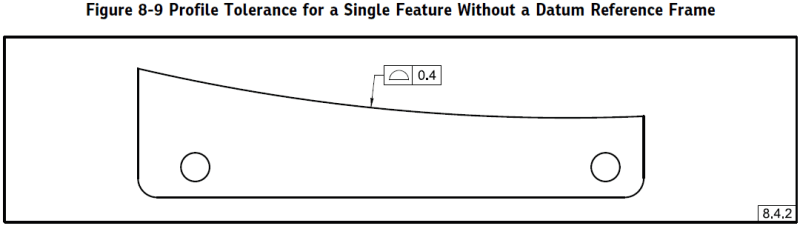
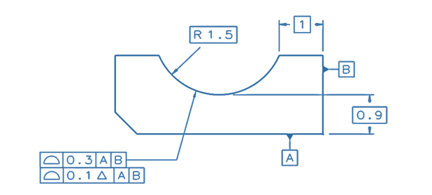
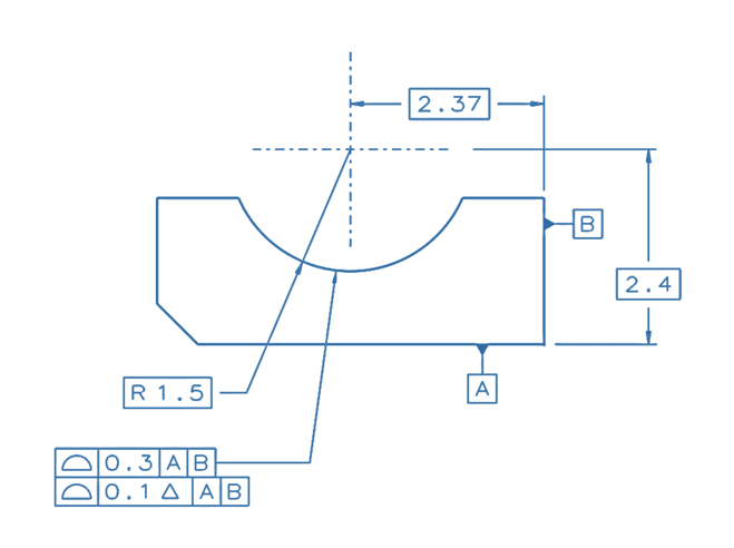
There is an example that was specifically designed to address the type of case being discussed in this thread. It's a single arc-shaped feature with a datumless profile tolerance:

Fig_8-9_from_51-2019_nhrcbm.png


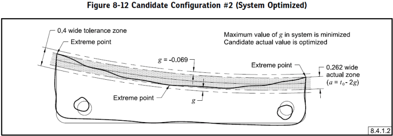
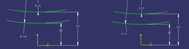
What does this control? The feature is not even close to opposed, so it doesn't really have "size". If we look at the final "means this" figure, we can get an idea:

Fig_8-12_from_51-2019_mj3obl.png


The as-produced surface is roughly arc-shaped, but its radius of curvature is smaller than the radius of the basic surface. The tolerance zone is a rigid body so it can't transform to adapt to this. We can see that if the curvature was much tighter, the surface wouldn't fit in the zone. In other words, the zone is arc-shaped but it won't accept an arc of any radius.

I would say that this zone controls form and curvature. In the text we ended up saying that it controls form and size, to be compatible with the language that Y14.5 uses. But really, it's form and curvature. In the end it doesn't really matter what words we use to describe it, because the original zone definition (rigid boundaries centered on the true profile) tells us what we really need to know.

This also means that curvature is not part of form. I believe that this is consistent with other definitions in Y14.5. Let's say we had a cylindrical feature with a size tolerance of 25 +/- 1 and a cylindricity tolerance of 0.1. Cylindricity is a form tolerance and does not control the size, or the curvature, of the feature. So the feature could be produced at a size of 100 mm or 10 mm and still pass the cylindricity tolerance - the cylindricity zone is not rigid. If the feature had a basic diameter and a profile tolerance, this zone would be rigid (centered on the true profile) and would control the size/curvature as well as the form.


Evan Janeshewski

Axymetrix Quality Engineering Inc.
 
axym,
I'm a big fan of the "SLOF" idea, it breaks down all tolerances to just 4 easy to grasp categories, with each geometric tolerance controlling one of these main properties or (more often) a combination of some of these 4. It allows explanations of the concepts to co-workers to be concise and clear. Until now, I was sticking to the idea that for features without size, a regular datumless profile controls form only and that form for such features includes curvature. I realize form doesn't control curvature if judged by cylindricity and circularity geometric characteristics. But another example is flatness. While being a pure form control, flatness keeps the curvature of the surface close enough to zero and prevents it from curving. Yes, according to my approach there might be an inconsistency between the meaning of "form" between arcs without size and cylinders, but in my mind it is still less confusing than associating a feature without size with "size".

So personally I think that "In the text we ended up saying that it controls form and size" is a bit unfortunate, and since Y14.5.1-2019 supports the 2009 version of Y14.5 which doesn't include the dynamic modifier yet, I'm not sure that there is a place in that version of the standard where the term "size" can be understood to describe a property of an arc without opposed points. Is there?
 
Burunduk,

The form-size-orientation-location breakdown works very well in most situations. Definitely for many traditional "GD&T 101" characteristics. But the limitations show themselves quickly in other common cases. When we get to things like coplanarity or coaxiality, there are no datum features but there is still the idea of orientation and location control. But it's relative orientation and relative location.

I agree that saying that datumless profile controls form and size was unfortunate, and we will need to address this in the next version. I don't think that we should apply the term "size" to a non-opposed surface. I agree that "curvature" is a much better term, but it's not ideal either because form-only tolerances still control the curvature in a certain way. So I'm still looking for a better term. It's really something like the absolute variation from the basic surface, whereas form is the consistency of variation from the basic surface.

Now I think we're in a better position to discuss dynamic profile ;^).

Y14.5 states in section 11.10 that the function of dynamic profile is to "allow form to be controlled independent of size" and all of the examples involve closed features that have a size-like aspect. This doesn't give much guidance on how it would apply on non-opposed surfaces that don't have size. We need to focus on the zone-based part of the definition in 11.10 that follows:

"When the dynamic profile tolerance modifier is applied, the zone is permitted to progress (expand or contract normal to the true profile) while maintaining the specified constant width (distance between the boundaries)."

This is the principle that defines dynamic profile. It's exactly like "regular" profile, except that the zone is allowed to progress. That's it. We can apply this definition to any type of true profile - opposed or unopposed. We don't have to worry about whether or not the feature is a feature of size, what size really means, or what form really means. Define the profile tolerance zone in the usual way and then it progress. This might result in some strange things in certain cases, but the meaning is clear and applicable in a general way.

I sure hope that dynamic profile can be applied to non-opposed surfaces, because we included an example of that in Figure 9-5 of Y14.45-2021 Measurement Data Reporting ;^).


Evan Janeshewski

Axymetrix Quality Engineering Inc.
 
axym,
I don't see a big issue with relating datumless profile for coplanarity or datumless position for coaxiality to the "SLOF" concept. I say that they control internal orientation and location, which is not the same thing as external (to the controlled feature or group of features) orientation and location - only an external control requires datum references. By the same token, a CF modifier could be added to a form or orientation control that applies to a flat interrupted surface, and all of a sudden there is an orientation and location aspect to a form control (equivalent to coplanarity profile), or a location aspect to an orientation feature control frame. But these are internal relationships, so - no big deal.
I believe that explanation of everything only in terms of the tolerance zone would be difficult and less comprehensible to the learning person.

The problem with applying the dynamic profile modifier to features without size, such as arcs without opposed points, is that in certain cases where it would work fine for features of size, it would become inapplicable for a comparable feature without size;

In this first example below, the dynamic profile controls form, orientation and location of the cylinder, independently of size (curvature), as described in "11.10.3 Dynamic Profile Tolerance Applied to the Lower Segment of Multiple Single-Segment Feature Control Frames".
D.P._EXAMPLE_1_tea2ar.png


In this second example, the part from the above example is cut so that only a portion of the cylinder remains as an arc with no opposed points, and now an attempt to control the feature the same way will result in failure, because the location constraints relative to the datum reference frame makes the requirement of the dynamic tolerance zone to progress normal to the true profile inapplicable. The basic distances of 0.9 and 1 have to apply to the true profile for both the dynamic 0.1 tolerance zone and the 0.3 tolerance zone.
D.P._EXAMPLE_2_vuanyk.png
 
Burunduk,

The 0.9 and 1 basic dimensions in your second drawing locate the true profile but they do not technically locate the tolerance zones. The tolerance zones are created from the true profile as follows:

1. The 0.3 tolerance zone is created by uniform offsetting the true profile 0.15 inside and 0.15 outside.
2. The 0.1 delta tolerance zone is created by uniform offsetting the true profile 0.05 inside and 0.05 outside and in addition by allowing it to progress away from the true profile by an undefined distance while staying 0.1 wide.

Out of curiosity, is there a specific reason why you did not show the 0.9 and 1 basic dimensions as 2.4 and 2.375? I hope you don't think that the method of displaying basic dimensions affects the interpretation and applicability of the dynamic profile tolerance zone mechanics in any way.
 
pmarc,
No, I really don't think that the method of displaying basic dimensions affects the interpretation and applicability in any way.

I do believe that there is a principle difference between closed and non-opposed shapes that relates to how they behave under locational variation. A closed shape is in the intended location relative to the datum reference frame as long as its center is properly located, even if the edge distances vary due to the progression allowed by the dynamic profile definition. An arc as shown in the example is technically not kept in the intended location, which is supposed to be controlled by the dynamic profile segment per sub-para. 11.10.3, if the dynamic profile zone has to progress from the true profile in the range allowed by the 0.3 tolerance zone to contain the as produced feature.
 
Burunduk,
So if you don't think that the method of displaying basic dimensions affects the interpretation and applicability of dynamic profile in any way, then for the sake of further discussion I propose changing the 0.9 and 1 basic dimensions to 2.4 and 2.375 so that your both drawings look as similar as possible.

With that change made and in the context of location, how is it that for the closed contour shown in you first drawing you seem not to have any issue with the dynamic profile FCF, but you apparently have issues with the corresponding profile FCF in the second drawing? I hope you will agree with me that in both cases the dynamic profile FCFs don't control location of the feature surface relative to the DRF. So is the first application correct to you because you think of location as of location of the feature's derived element - axis in this case? If so, why would we need to think about it this way in case of profile tolerancing?
 
pmarc,
This makes little difference exactly because the basic dimensions can be given in various ways resulting in the same definition, but the following figure is an exact equivalent of the second example from my post in 5 Mar 23 06:50.

D.P._EXAMPLE_2_ALTERNATIVE_DIMS_1_bjv44v.png


I am guilty of paying close attention to what the standard has to say, and I think that the relevant paragraph is "11.10.3 Dynamic Profile Tolerance Applied to the Lower Segment of Multiple Single-Segment Feature Control Frames". The text specifies that "When the dynamic profile tolerance modifier is applied in a segment of multiple single-segment feature control frames and includes datum feature references, the tolerance zone is constrained in translation and rotation, but not size, as applicable.".

If the dynamic tolerance zone has to be constrained in translation, it can not progress/move from the exact location defined by the basic dimensions 2.4, 2.375, and R1.5, which in this case work together to locate the true profile relative to the DRF, while R1.5 also defines the form/curvature. The basic dimensions could also be given as in the original version of the example, and it wouldn't matter. "The tolerance zone is constrained in translation" essentially means that the 0.1 "dynamic" zone is fixed to be centered to the basic arc. Whether this is the fault of how the description in the standard was formed or of the decision to apply this concept to this type of feature is subjective, but this shows the existing problems. And it's part of the reason why I originally said that the modifier only makes sense for features of size. If we wish to apply it to any feature, we can try, but not without consequences.
 
Burunduk,
I am afraid I am not following you. If this is the interpretation you want to use to argue that the dynamic profile tolerance zone for the non-opposed arc doesn't have any ability to progress away from the true profile, thus the application is invalid, then why don't you see the same problem in case of your first example with the fully closed circle? Is it now because the hole "size" in the first drawing is defined with a basic diameter and not with a basic radius?

 
pmarc,
In the first example, basic ø3 defines the size of the cylinder, but not its location. The location of the cylinder is defined by 2.4 and 2.375.

In the second example dimensioned as in the second version by 2.4, 2.375 and R1.5, all three basic dimensions combine to define the arc's location relative to the origin of the datum reference frame, including the radius.

Here is a question - if a radius of 20° arc floats in space relative to its original placement but keeps its value (for example R1.5), do we say it dislocates/translates? I suppose the answer is yes.
If the same radius remains concentric to its original placement but changes the radius value (progresses) do we no longer say it dislocates/translates?
 
pmarc, let me illustrate the above question.

arc_loacations_op2i0g.png


The 1.5 and 1.6 arcs on the left are concentric. The H and V axes represent the measurement origin. Would you say that the left side image shows two arcs in the same location relative to the origin, while the image on the right represents two arcs at different locations?

If the answer to the above question is yes, does this mean that the only thing that you consider meaningful for the 'translation'/'location' of an arc-shaped/circular feature is the location of its center?
 
Status
Not open for further replies.
Back
Top