Continue to Site

Eng-Tips is the largest engineering community on the Internet

Intelligent Work Forums for Engineering Professionals

  • Congratulations SDETERS on being selected by the Eng-Tips community for having the most helpful posts in the forums last week. Way to Go!

New start material strenght calculation for operating horn from crashed plane. Part 2 4

Status
Not open for further replies.

RedSnake

Electrical
Nov 7, 2020
11,333
Can anyone help me check if this calculation works so far?
There are so many conversions between different units ..
The calculation is made by a free software but I assume that their calculation models are correct.

My own assumption is that the elevator is heavier at the front edge as there are hinges made of MIL 1430 N and since the lever and its attachment also are , there are also steel details on the other side and the rest is aluminum.
I have chosen to see it as a simple bar to begin with.

And the calculation is made to check which load the fixed joint must withstand for the elevator's own weight.

I intend to present it in steps so if I got something wrong I can adjust it before the next step.
If it's okay with you people?

Best regards Anna

“Logic will get you from A to Z; imagination will get you everywhere.“
Albert Einstein
 
Replies continue below

Recommended for you

Step 1

v%C3%A4rden_h%C3%B6jdroder_gwenxx.jpg


Length of Beam L= 258 mm (Mean Geomatric Cord av 20.7898 tum (inch))
Young's Modulus E= 205 000 MPa
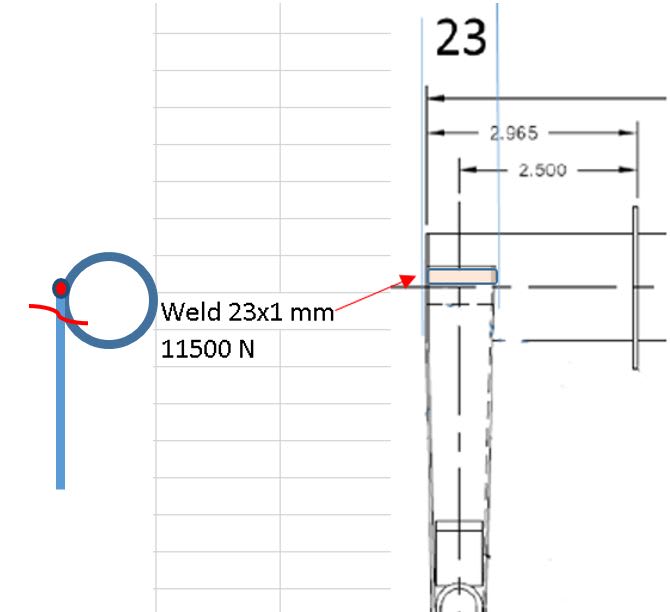
Area of Cross Section A= 23 mm (1 mm x 23 mm = 23 mm The only thing that holds the beam at the fixed support 76 mm)
Second Moment of Area (Moment of Inertia) Ix= ??? mm4

Second_moment_sxcfc5.jpg


Is this torsion or moment?
And what then becomes height h and width b in this case?
Where the fracture occurred, the material thickness is 1 mm, but what then counts as height?

I went for this but I'm not sure that's right
Ix=(1/12)*h*b*b*b =(1/12)*23*1*1*1= 1,92 mm4

Second_moment_1_ipyadz.jpg


Best regards A

“Logic will get you from A to Z; imagination will get you everywhere.“
Albert Einstein
 
It may be productive to consider the steps in the progressive failure.
For instance, if the elevator was torn loose by aerodynamic force before the weld broke, the strength of the weld is moot.
Also the direction of the forces on the weld are unknown.
Some of these points are known, some may be speculated by the nature of the damage and some may remain unknown.
Did the stabilizers separate from the aircraft?
Did the elevators separate from the stabilizers?
Where are the travel stops located?
If the stops are on the elevator itself, then the pilot may have been able to break the weld.
If, however the travel stops were located and acted on the horn itself or on the linkage, then once the movement reached the stops, the pilot could not have caused extra force on the weld.
Any excess force would be restrained by the stop.
Once on the stops, the only force on the welds would be aerodynamic force.
Consider the damage to the push-rod and the threads.
The damage to the push-rod suggests either compression or bending after the assembly left the aircraft.
The damage could not have happened while the assembly was in position.
If the threads broke first, that would remove the force on the push-rod.
If the push-rod buckled first, that would relieve the force on the threads.
I have to believe that the damage to both sides was a result of aerodynamic forces as the craft broke up and strength calculations in regards to the weld are moot.

Did the plane fall nose first, tail first or was it tumbling?

Bill
--------------------
"Why not the best?"
Jimmy Carter
 
I have the answer to most of these questions.
But in order for me to be able to do the strength calculation myself and understand it,
I have to start from the beginning and keep it simple and then build on with more conditions as you suggests ..
Right now I just need a foundation to build on.
I'm sorry if this makes it too cumbersome or possibly too easy for you guys (assumption) ..
I hope you can put up with me and my questions.

It's a lot about that fact that I need to understand how the strength calculation is to made, not about the accident ..
And if I do not get a real answer in the end,
If nothing else I have learned a lot of things that I might be able to use in other contexts.

I have an answer for you Waross to a question you had on a thread at.
Link

Best regards A

“Logic will get you from A to Z; imagination will get you everywhere.“
Albert Einstein
 
Thanks Anna.

Bill
--------------------
"Why not the best?"
Jimmy Carter
 
For a 1 st order approximation, I would

Consider the weld thickness to be the thinner of the two materials welded together. The material thickness for the tube is likely incorrect as 1mm isn't a stock thickness for the torque tube (they are very unlikely to have used a non standard tube thickness, typical tube thickness
Assume the moment is resolved as a force couple placing one of the two 23mm welds in tension and the other in compression.

The allowable stress for the weld material is should be taken from MMPDS, chapter 8. It doesn't tend to change from version to version so values from MMPDS-01 should be fine

You have assumed that all of the moment is resisted by a single weld, this would be the case after the weld around the rest of the box section has failed completely.

So roughly, the moment capacity looks like = Weld Area (on one side of the tube) x Weld Allowable x tube diameter


The distance from the hinge line etc only matters when it comes to calculating the applied load.

For calculating the load on the elevator have a read through this, the key bit is Figure A7.
 
verymadmac said:
The material thickness for the tube is likely incorrect as 1mm isn't a stock thickness for the torque tube

Then I make an assumption that it is 03-08800, 1 1/2, 0.035, 1.430, 0.548 (outer diameter 38 mm thickness 0.889 mm)

The reason why I have assumed that the only thing that holds this together is 23 x 1 is because the Accident Investigation Board did it.
I start with the same calculation model as them.
Namely I start from the same assumptions as them.

The lever is constructed of approx. 1 mm MIL 1430 N or more precisely MIL-S-18729C cold-rolled metal plates that are bent 90 degrees and then welded together to a rectangular tube, then welded togetherd with a round one.

According to the manual, repairs must be made in accordance with AC 43.13-1B.
Which states that AMS 6457 is to be used.
This is not a repair, but I assume it is the same welding material used in the manufacture.

steel_kvalite_pljcla.png

The fraction is not in the weld, probably in the HAZ area, but I have ignored it because the Accident Investigation Board has done so.

tabel82211_ohipo3.png


What does Fsu, stand for?
I guess that Ftu, is ultimate tensile strength ..

Best regards Anna

“Logic will get you from A to Z; imagination will get you everywhere.“
Albert Einstein
 
Anna,

I think you really need to use two welds in your analysis. I know the board sort of had one, but they weren't really looking at whether the system held up ok. Only one weld is not a realistic scenario.

In terms of forces etc on the elevator, don't forget that the elevator has a counterweight (with a pre formed lead weight in it) at the far end to reduce elevator forces. The resultant force / weight at the training edge is between 0 and 1.2kg max

Also your beam for the arm tapers so the second moment of area (I) changes as you go from one end to the other.

And you need to find the equation for a square box section, not a solid bar, which is what you have at the moment.

Remember - More details = better answers
Also: If you get a response it's polite to respond to it.
 
LittleInch said:
I know the board sort of had one, but they weren't really looking at whether the system held up ok.
That was exactly what they did, or claimed it did.
However, I do not know for sure, if the reason was that the rest of the welds were unsustainable or if they just made it easy for themselves.

I plan to start with one and then increase to 2 welds or more. But right now I have to understand the basic principles ..

One step at the time :)

LittleInch said:
forces etc on the elevator, don't forget that the elevator has a counterweight (with a pre formed lead weight in it) at the far end to reduce elevator forces. The resultant force / weight at the training edge is between 0 and 1.2kg max
I know of this counteweigt and I will do my best to compensate for it when I get there.

LittleInch said:
Also your beam for the arm tapers so the second moment of area (I) changes as you go from one end to the other.
In step 1. I only look for the static weight of the elevator when resting on the lower stop as in the picture above

LittleInch said:
And you need to find the equation for a square box section, not a solid bar, which is what you have at the moment.
Right now the only thing I have is a sheet metal plate thickness of about 1 mm welded to a pipe wall thickness of about 0,889 mm with a 23 mm weld. ;-)

I can not start running until I have learned to walk... And you're running too fast for me..

Right now I wounder what does Fsu, stand for?

Best regards Anna

“Logic will get you from A to Z; imagination will get you everywhere.“
Albert Einstein
 
The issue is that the 5 g is loading due self weight. So what's the weight of the elevator?

A pilots loading is meant to be 35kg pull or push (please don't get into if this is realistic) with a gearing ratio of x 5 that mean sit can apply 170kg on the elevator round numbers with a 1.5 safety factor.

so even if the elevator is 5kg which I would be utterly amazed at then that would be 25 kg at 5G. You really don't need much weld to hold 500kg which is why i suspect they have bypassed quite quickly that side of things.

V sqrt on the other hand if its against the stops at Vne and design limited at 170kg doesn't have to increase that much to go well over designed load without safety factor.
 
Mass = 6,758 kg
Weight = 6,758 * 9.81 = 66,3 N
Weight at 90 degress = 69,3 N , 0,0693 kN
G +5,7> 69,3 * 5,7 = 38,52 N

But the weight can be for both halves I became a little unsure now :-(

inst%C3%A4llning_elevatorJPG_vunem2.jpg


Maybe this helps? ..

/A

“Logic will get you from A to Z; imagination will get you everywhere.“
Albert Einstein
 
Aye but compare to 35kg at x 5 gear ratio its next to nothing. Put in x 1.5 safety and even less. You can have 5 fat scaffolders standing on 10 cm worth of weld and it not fail.
 
This is just an example so you do not have to worry about the numbers.

But if the weld can be calculated to hold for 352 * 23 = 8092 N (AMS 6457, 51 ksi)
And the reaction is R -0,0208 kN at the lever in this example, = 208 N

So it is not a problem as Alister says.
Then I would have 7884 N "to handle the rest" ??

I'm just trying to understand if I got it right.

Exempel_1_trbowh.jpg

Exempel_2_yvgtct.jpg


Best regards Anna


“Logic will get you from A to Z; imagination will get you everywhere.“
Albert Einstein
 
To be honest in 1996 I failed a Phd in research in welds in Nuke reactors for loading lugs internally on pressure vessels. Because basically I realise that line of things wasn't for me and I really couldn't be bother writing up. The research was used though for ASME codes for current reactors. If any one wants look it up it was published by Prof Grey and Prof Boyle and I think Mackenzie. if you search on my name for papers the rest of the family will come up, my mother in education, dad in health physics and sister in microbiology. I think I am mentioned in a few but they will swamp me. Dad and sister are Phd's so me and mum will more than likely only have a couple of hits.

I don't want to claim any engineering expertise in the forum because I am so out of currency.

Basically you have 4 modes of failure of a weld.

1. shear ultimate failure.

2. tension ultimate failure

3. ductile tearing

4. Fast facture due critical crack intensity exceedance.

With normal linear computational methods you can only pick up the first and second failure mode.

The other two are none linear geometry failure modes which are extremely hard if not impossible to predict without running finite element analysis done with someone with half a clue about nonlinear materials and also fatigue.

The way the forces work in this item is so none linear in geometry I could in my day have 3-4 computers running 24H and then have to restart them after getting an ill conditioned matrix due to the boundary conditions being out and having to tweak them. While running I would set up a physical test with strain gauges to confirm the linear part of my model which the modern FAE peeps don't seem to bother with.

In this situation number 4 is out because no fatigue fracture surfaces have been reported.

Number three the load is so controlled in its direction you can't get into the range of angles that would make ductile tearing a feature.

1 and 2 the amount of weld that needs to be good for the weld to hold is scary small for the amount of load that is required. The 5 fat blokes standing on scaffolding is a concept I have used many times over the years to have a sanity check on the amount of weld to throw at things if it seems too small.

If there was fatigue surfaces reported then I would say the weld was under designed and higher than predicted load. No fatigue surface means its inside the design specs for a service life after 8 years hard hard use as a para dropper which is above normal load. If it had been in the 70% yield strength part of the SN graph I would expect some growth cracks and some fracture surfaces.

Right I am now going back to being a stick monkey :) xxx the real Engineers reading this please don't be too critical it been a long time since I signed anything off .

 
Alister or someone..
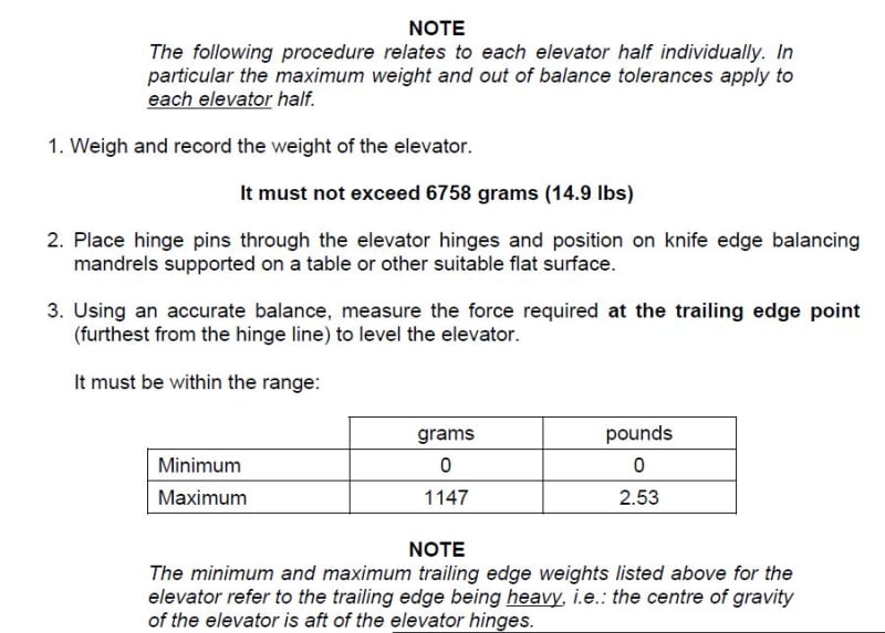
I am correct to a assume that if the elevator is balanced to 0 grams then the weight of the balance horn and the eleavtorn is the same on both sides of the hinge?
And if not the elevator must not weigh more than 1,147 kg more?

Best Regards Anna

“Logic will get you from A to Z; imagination will get you everywhere.“
Albert Einstein
 
yes that's the way I read it.

The balance horn is the bit forward of the pivot point. They go out of balance as paint wears off them. They stick little weights on them like they do with car wheels (in fact its the same weights)
 
Thanks !

So do you have the weekend of or are you betwen jobbs if a may ask ?
I have some questions about constant speed propellers if you or someone else is up for it

friday_x2rwts.jpg


Or it could have been :)

Best regards A

“Logic will get you from A to Z; imagination will get you everywhere.“
Albert Einstein
 
Just finished a working block... And as much as we tried to keep the cabin crew happy we couldn't go tech in Cyprus. 25 deg's with a nice wind coming off the sea was lovely.

And i am well up to speed on variable pitch props. Ask away.
 
Okey :)

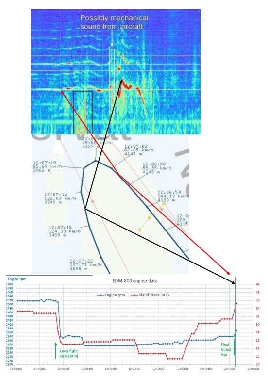
First I will try to explain what you see here. It is an audio recording of the plane during the accident. According to the sound file, the speed from the propeller was fairly even around 2350 rpm before the plane dived down to the left.
The lowest speed after that was about 2000 rpm and the highest about 3100 rpm. The maximum for the plane is 2700 rpm.
Ljudsekv_biblur.jpg


My assumption is, and now you or someone else must correct me, if I'm wrong.

When the airplane pitch down to the left, there is overspeed so the governor will increase the pitch of the blades so that the engine slows down to set speed approximately 2350 rpm, which happens about 07:10.
And then there is underspeed after where governor will decrease the pitch of the blades to so that the motor can speed up to the set speed again, approx. 2350 rpm.

But for the engine/propeller to reach 3100 rpm, one of these three things must have happened.

1. Someone inside the plane pushed the propeller control lever forward.
2. The oil pressure was loost so that the spring behind the propeller hub piston forces the piston forward and it becomes low pitch/high RPM setting.
3. The the flyweights in the governor broke so that the pilot valve moved down and oil flows out of the propeller hub, reducing the pitch of the blades.

Or is there any other way this high rpm for the propeller/motor can be reached without anyone changing the seetings inside the plane ??

Best Regards Anna

“Logic will get you from A to Z; imagination will get you everywhere.“
Albert Einstein
 
The which way it will go with oil pressure loss is dependant on the propeller make and national philosophy of if its preferred that the prop feathers in the event of an engine failure resulting in loss of electrical power or continues to turn but creates a huge amount of drag. Propeller is separate to the engine. So with the same engine it might be different between different makes and models. Some have a sperate oil system with a gear box driven pump and backup electrical pump. It very hard to unfeather a prop and they usually build in a method to be able to do that.

Well there a few things that can cause it

The spline shaft couple between the prop shaft and gear box can go. Or the one between engine and gear box. If that's how they have connected them on this aircraft. They put in sacrificial connections so if there is a prop strike it won't rip the front off the front the aircraft and or the engine out of its mounts. They sometimes go but very rarely without having a prop strike. They are inspected every xxxx time period defined by the maint schedule. Its not something a pilot would look at.

Also the one that I suspect happened which is, this is not a negative G engine. It won't have scavenger oil recovery system or a pressurised oil tank. There are a few other features which are required so it can be. There are very few aircraft that can manage to stay in negative G more than a few seconds even with all the negative G kit. Normal fit none acrobatic aircraft things start happening at 0 G pretty much instantly.

If you go negative G the oil system starts sucking air and there is then a cascade of things start happening. And if its a prop which goes fine pitch on pressure loss then the over speed governor will loose control of the prop speed and with full throttle it will red line. There is usually two OSG's one on the prop system and one on the engine itself which will cut the fuel flow if it goes too high.

And one of the first things you do with a flight upset with a variable pitch prop is to max the rpm. Which gives you max power and also max drag if required. But I suspect that this all happened too quickly and there was to many G force changes in strength and directions for this to have happened.


Status
Not open for further replies.

Part and Inventory Search

Sponsor