Eng-Tips is the largest engineering community on the Internet

Intelligent Work Forums for Engineering Professionals

Newly Constructed Gym Has Roof Collapse in New Mexico 12

Status
Not open for further replies.

jerseyshore

Structural
May 14, 2015
702
0
16
US

gym1_jzeshz.png


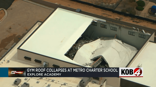
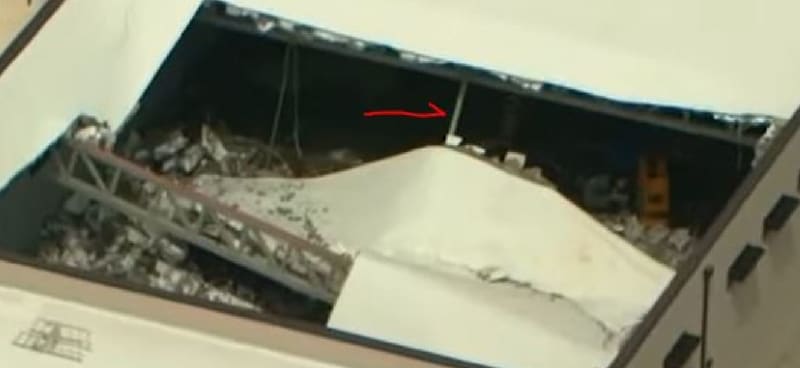
ALBUQUERQUE, N.M. — In-person classes have been canceled at a local charter school for the rest of the week after the roof of its new gym collapsed.

School officials say the new gym at the Explore Academy middle and high school campus was basically complete. They were even planning on hosting a ribbon cutting Wednesday, but that’s been canceled, as well as all in-person classes.

Parents learned about the collapse through an email from the school Sunday night.

“The students are out the whole week now,” a parent told KOB 4 anonymously. “Because they have to get inspectors to gather and, at the request of the inspectors in particular, for students to stay away until they can just look the whole thing over.”

The parent said the incident has raised many more concerns about sending her child back to school.

“Students were going to be in that building in two days, and I think one of the big questions I personally have is, did it pass the inspection already?” the parent asked.

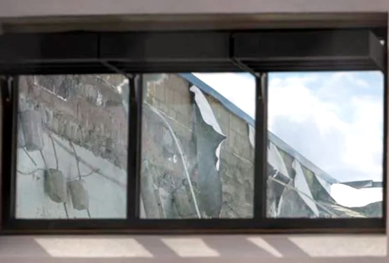
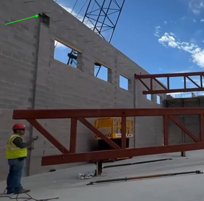
The answer is no. KOB 4 spoke with a rep from Albuquerque’s Planning Department. They said the construction company, AIC General Contractors, failed a building frame inspection on March 6. Inspectors found the trusses bowing or bending.

The city’s Planning Department didn’t know the roof had caved in until KOB 4 called Monday afternoon.

Explore Academy leaders say, as of now, it’s just the new gym that seems to be impacted, but they aren’t taking any chances.

“They discovered the damage and evaluated the situation and decided that we would go ahead and go to asynchronous learning until we have a sign off that the entire building and structure is, in fact, safe for students to enter,” said Katia Pride, Explore Academy’s director of outreach.

Pride said there was no obvious damage to nearby classrooms. The school will also have to bring in an engineering company to create a repair plan.

The city’s Planning Department will be sending a building complaints investigator to figure out what went wrong.
 
Replies continue below

Recommended for you

I also don't think the pilaster was the problem. However, the depth of the block/pilaster affects the available bearing surface and degree of eccentricity. Given the construction method, the bearing surface is limited to less than half the pilaster depth.
 
Brad said:
OK, image below is NOT totally accurate,

That image whilst maybe not 100% accurate makes more sense than a separate block.

If it was like what you have shown, the failure makes more sense - The outer wall of the block could have broken off, leaving little support.
 
Did anyone submit a public records request yet for the plans with the City of Albuquerque? This thread is going to re-engineer this whole structure 10x over before we get any new info I bet.
 
Permit plans would be nice, however no guarantee they match as built. We also need approved shop drawings for the truss.

They are keeping quiet on this whole thing, which smells like all parties involved are concerned about their role in this.

Everybody hunkering down in preparation for litigation. Without whistle blower we may not get any more information for a long time.


roo3a_fkgg27.jpg


What is this? Someone above mentioned the roof panels may have fallen on a construction lift. Could it be something else? From another angle this (steel) piece is inclined at a large angle from the vertical, so it wouldn't have been a vertical brace. Could it have been a steel beam, added later when unusual deflections were noticed, connecting the bottom chords of the trusses together to provide lateral support? The location looks to be exactly at midspan.
 
From a construction/build standpoint alone, I don't see how you can set the hollow core concrete roof planks without some temporary lateral bracing for the two long span trusses. You would have to set them in the correct install pattern sequence, to avoid 'tipping' the truss. Once truss is tipped out of plane, oh no!

So if lateral bracing likely required for installation, and hollow core deck ends, which appear to be a friction float on the top chord of truss, would 'tip' with any load differential between opposing ends of hollow core planks.

It appears GreenLama is onto something, and a lateral mid-span brace may have been added for construction or resolution attempt after failed framing inspection?

The two steel cables showing thru windows on parapet wall is odd as well?

Classic Example of where a Good System Engineer Construction Manager working solely for the Customer paying the bills is employed to catch the disconnects between design throwing it over wall to GC, and GC then has to figure out how to actually assemble the design safely, and in proper order.

A Great System Engineer/Construction Manager, is money well spent. Now choosing poorly can also WRECK a project. I have personal knowledge of Practicing PE Structural Engineer Construction Manager, that saved his customer lots of $$$ over catching costly design flaws and build-ability issues of design. And this was huge Manufacturing Campus from ground up.

Edit: The kicker is he makes more money as CM than he does doing design work for himself. Now he is unusual person that has design expertise and vast Project Management Field Experience. So not every DEI hire has this level of talent, skills and experience.

 
SymPIe, I'm not saying this would have been a good idea. The slenderness ratio would have been huge. And, since both trusses are identical, have identical loads, and identical boundary conditions, if the primary buckling mode pushes center span point out, you would just get both trusses to buckle simultaneously.

The report you noted above says they noted a dipping of the truss. No mention of a horizontal component. But that doesn't mean there wasn't any.

If this is a retrofit, it reminds me of the FIU bridge collapse. They have a nearly completed structure that suddenly shows signs of unusual movements. So, to try and salvage it, and keep to construction schedule, they go in and start trying things, without fully understanding the issues. All this does is put construction workers lives at risk.

There's a lot of speculating here. The way the roof panels fell it just appears that they break across the midspan, implying something substantial running beneath. You can envision a case where the two trusses start moving towards each other at the midpoint, and someone says, Hey, all we have to do is block them somehow.
 
Based on the assembly video, it's not clear if the bearing engagement on each protruding pilaster was equal, and this may have influenced the failure mode. After engaging the left support, the free end of the truss sweeps just inboard of the other, protruding pilaster. The truss must then be moved longitudinally to engage that bearing surface.

I believe this questionable truss support is the one that lost engagement at the time of the collapse, while the other end was still supported. Check out time interval from 0.20 to 0.25s


I don't think this illustration of a truss end support can be relied on, as the actual one is a proper, protruding pilaster.


Kevin Kelleher, P.E. (retired)
Internal Mechanical Eng'g Consultant
DuPont ESD Specialists
 
KevinK2 said:
Based on the assembly video, it's not clear if the bearing engagement on each protruding pilaster was equal, and this may have influenced the failure mode. After engaging the left support, the free end of the truss sweeps just inboard of the other, protruding pilaster. The truss must then be moved longitudinally to engage that bearing surface.

Agreed. The long truss was swung in horizontally, between the walls, leaving marginal support at the edge of the pilaster.

Thermal movement could also potentially have pulled/torn the flimsy edge.
 
In addition to video not showing adjusting bearing depth on last end of truss, how much of the bearing margin depth was lost by swinging trusses into pockets with parapet wall already built, versus dropping trusses in from above before parapet wall built on top of bond beam?

Pocket had unused bearing depth closer to centroid than swinging technique allows utilization of.

Pockets are common on tilt-up reinforced concrete wall panels, however those walls are stronger and more durable than spliced rebar stuffed into grout filled cinder block cores. Especially outer face of cinder block.
 
LittleInch said:
If you're interested in the full constructon time lapse see here

Is there a real time video available? May provide more details of what appears to be steel lined openings for the pilasters, and how the workers were using fasteners? to secure the end of the truss.


Kevin Kelleher, P.E. (retired)
Internal Mechanical Eng'g Consultant
DuPont ESD Specialists
 
I have seen the full 31 second video on Facebook, and my eyes don't see a steel lining on pocket, and I offer up the fact that they enlarged the pockets during erection. Those images were posted above and I will post my adding arrow to one of those pictures below, showing they chiseled out the side of pocket to enlarge it so truss would swing into place. Later images show the pocket growing even more than what is pictured here..... They did not chisel thru steel, IMHO.

b1_cypnhm_burtlp_bbcwkp.jpg
 
I wonder if the original design featured the truss top chord extending into the wall, which might have been shortened later for constructability reasons. It's hard to imagine a designer intentionally allowing the truss to bear only on the outer edge. It's plausible that the designer might have assumed the trusses would be set into pockets, without realising that the builder was going to construct the walls in one go, preventing full length trusses from being dropped in.

We've definitely encountered scenarios where the shop drawings include subtle modifications for easier construction - things shorted a little, etc - and these changes go unnoticed by those reviewing and approving the shop drawings. Then you arrive on site and realise there's a potential problem. Sometimes, these changes are significant and aren't caught by anyone (eg Hyatt walkway collapse)

Of course, this is just speculation, but it's a scenario I've seen play out based on my experience.
 
My thinking is steel trusses were very long lead item, and the GC did not want to have to pay mason to re-mobilize for parapet wall as separate step, and did exactly what you have seen, and school was pressing to compress schedule so they bought in on what may have been a read bad decision?

Bearing plate should be sufficient, IMHO.
 
Tomfh said:
I wonder if the original design featured the truss top chord extending into the wall, which might have been shortened later for constructability reasons.

It does seem like the top cord was initially too long to fit into the original pockets, based on the left pocket apparently being manually deepened. This allowed the right end to swing inboard of the protruding, original pocket/pilaster. It may appear that opening was also widened, perhaps for installer satisfaction vs true function. The installation video shows this was not necessary.

The left pocket on the other previously installed truss appears to have also been deepended (but not widened).

Q: Why didn't they lift the truss, with both ends on the other side of the pilasters? Then the far chord could have been slid horizontally into the open end of the pocket, vs outside of it.

It's hard to imagine a designer intentionally allowing the truss to bear only on the outer edge.

Q: By outer edge, does this imply line contact across the width of the cord, at the outer edge of the bearing surface? Hard to control where line contact will occur, based on camber at cord end and plane of the bearing support.


Kevin Kelleher, P.E. (retired)
Internal Mechanical Eng'g Consultant
DuPont ESD Specialists
 
On the pilaster opposite of which has been posted a few times,you can see what appears to be two studs protruding up through the bearing plate, as well as what appears to only be 3" to 4" of bearing area as they sat it down. Without any room to get in from behind, I cannot see how any bolted attachment of the truss to pads could exist. If it was a welded joint, would Aprox 4" of weld per side actually suffice here? Could 2 studs holding the plate down be enough to prevent tilting?

The whole arrangement to me looks like once they got it in there, they assumed it would stay once they blocked it back in.
 
Status
Not open for further replies.
Back
Top