Continue to Site

Eng-Tips is the largest engineering community on the Internet

Intelligent Work Forums for Engineering Professionals

  • Congratulations KootK on being selected by the Eng-Tips community for having the most helpful posts in the forums last week. Way to Go!

No lateral support at the supports of a beam 5

Status
Not open for further replies.

Logan82

Structural
May 5, 2021
212
Hi,

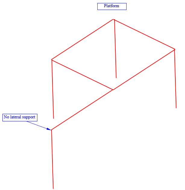
I have a situation where it is not possible to have lateral supports at one beam support of a platform. Normally it is standard practice to have lateral supports. Are there some reduction factors to apply to the resistance of this beam due to the non laterally supported beam support? There should be no torsion applied on the beam.
4_urx7gq.png
 
Replies continue below

Recommended for you

BAretired said:
KootK states he would be hard pressed to say the column braces the beam. Why is that?

Because stiffness is king in these situations and:

1) In my experience, most practical post cross sections used in situations like this will be challenged on the stiffness front.

2) The stiffness of the column top relies heavily on the rotational stiffnesses of the base connection, the foundation element, and the supporting soil, all notoriously difficult to predict reliably.

But yeah, sure, use an 8' tall W21x44 embedded in a 3' deep grade beam and I'm sure that we'd be off to the races.

My money says this is more like, at best, an HSS4x4 with four J-bolts and a 4' square footing with no top steel and no soils report.
 
I also think that this is a fine application for a shear tab beam to column connection rather than an "over the top" with stiffeners. Unless there's a compelling reason to do otherwise, it just eliminates one source of potential instability from an already complex situation.
 
KootK said:
But yeah, sure, use an 8' tall W21x44 embedded in a 3' deep grade beam and I'm sure that we'd be off to the races.

My money says this is more like, at best, an HSS4x4 with four J-bolts and a 4' square footing with no top steel and no soils report.

But in response to the OP's question, we simply don't know what the members are. Structural design should be performed, taking all factors into account.

KootK said:
I also think that this is a fine application for a shear tab beam to column connection rather than an "over the top" with stiffeners. Unless there's a compelling reason to do otherwise, it just eliminates one source of potential instability from an already complex situation.

A shear tab would not be my first choice.


BA
 
The column can provide some torsional stiffness to
beam but I agree it’s not great. It’s be nicer if lateral translation was prevented somehow, but you can’t do that….

I would make sure the beam itself can easily resist the lateral force, Eg is not prone to the mechanism kootk has drawn.

For the column/beam connection I would use a torsionally rigid connection, Eg stiffened cap plate, or end plate
 
BAretired said:
But in response to the OP's question, we simply don't know what the members are.

Sure, but sometimes you just have to go to war with the information you have, not the information that you wish you had. I stand by my recommendation based on my expectation of proportions here.

BAretired said:
A shear tab would not be my first choice.

What concerns you? As I see it, a shear tab:

1) Is common and easy to erect.

2) Will easily work for the loads involved.

3) Introduces a little more eccentricity in the column connection which I would deem a marvelous tradeoff in exchange for eliminating the rollover potential. Besides, even with the eccentricity my money says it's the buckling the other way that will govern the column by a long shot.
 
KootK said:
Sure, but sometimes you just have to go to war with the information you have, not the information that you wish you had. I stand by my recommendation based on my expectation of proportions here.

The title of the thread is "No lateral support at the supports of a beam" and the discussion proceeds without determining dimensions, loads and member sizes. The title is an inaccuracy. The question cannot be answered without getting the correct information. No sense "going to war" with the wrong information.

KootK said:
BA[/color]]
What concerns you? As I see it, a shear tab: A shear tab is not very stiff in resisting beam rollover.

1) Is common and easy to erect. Not an important consideration for a one-off.

2) Will easily work for the loads involved. We don't know the loads involved, along with a bunch of other stuff.

3) Introduces a little more eccentricity in the column connection which I would deem a marvelous tradeoff in exchange for eliminating the rollover potential. Besides, even with the eccentricity my money says it's the buckling the other way that will govern the column by a long shot. That is speculative at best. Rollover is not possible if the column, with stiffeners is effectively continuous through the beam.


BA
 
For the sketches, I simply used Microsoft Word 2010 to draw, then took a screenshot haha.

The platform is not a big structure, but it brought this question to resurface in my mind, as I am sure I will have to deal with something like this for a bigger structure later.

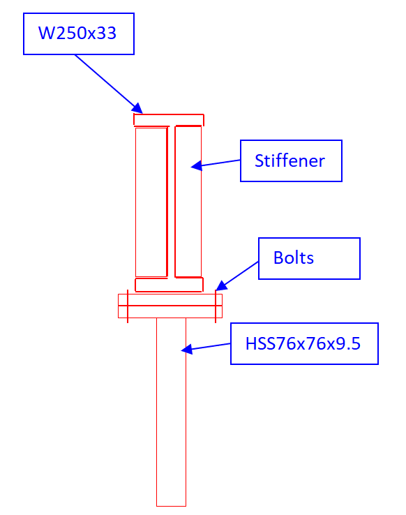
The platform columns are square HSS 76x76x9.5. The beams are formed of W250x33. At the base, there is an existing concrete foundation. There is a live load of 4.8 kPa. The connections are all moment stiff, for moment around strong and weak axis. Considering this, I would think that the design would work, since the beam on top of the "flagpole" has sufficient bending resistance on the weak axis. Sure, the lateral deflections might be big on the top of the pole, but I believe the section of the W beam on top of the pole is monolithic with the column since there are stiffeners. While this design sounded ok, my concern was in regard to the fact we never see bridges without cross-frames or diaphragms at supports.

For the first sketch (small platform), the column with no lateral support (that is no diaphragm or cross-bracing or orthogonal member in the horizontal plane) has a connection that looks like this:

5_rog4mc.png


Thank you KootK for the conservative calculation method ideas. In my case, I design it with a FEA structural software, so I consider this structure as working as a whole.


Logan82 said:
I think the lateral support at the support is required according to CSA S6 2014 Canadian Highway Bridge Design Code.

KootK said:
I don't feel that provision is speaking to the same thing. I believe that provision to be speaking to how discrete lateral loads are moved downwards from the bridge deck diaphragms to the piers / abutments below. And, where that is the situation for building diaphragms, the same would apply as a matter of common sense if not prescriptive requirement. The cases that you've presented for buildings seem to speak to questions of buckling prevention restraint which is a different matter in some important ways.
I think what you just said there is very close to the answer I was looking for. By buckling prevention restraint, do you think simply adding stiffeners would do the work (like in the detail shown)?

Also, in my case the floor on the top of the beams, so I feel like it is similar to a bridge with a deck on top of the beams.
 
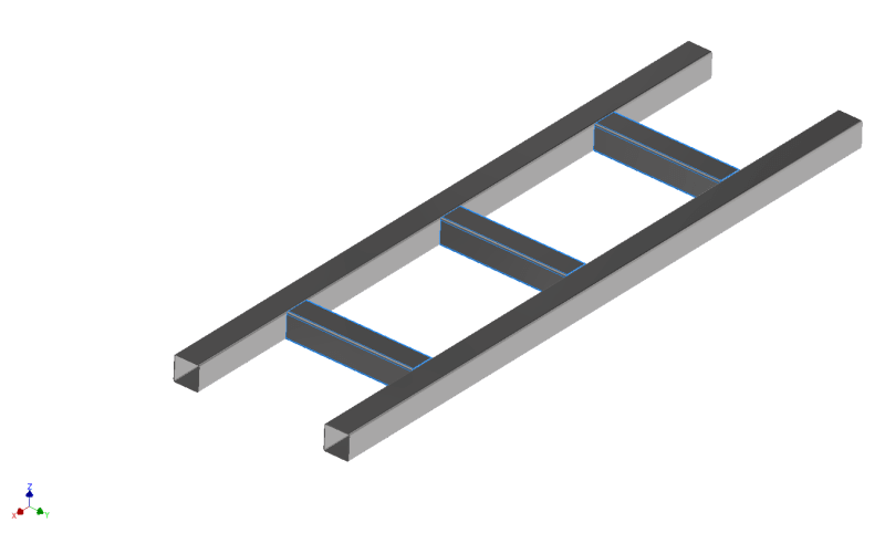
Also, say you have a bridge built of HSS beams, which are very resistant in torsion, would the clause requiring cross-bracings and diaphragms at the supports still be useful?

Could a bridge built like this theoretically work?
6_b82asg.png
 
I would use stiffened top plate like that, but can you also bump up the column size to make it stiffer against rotation?

76mm seems a bit small

As for that HSS bridge. It works. SHS don’t buckle.
 
Yes that column seems crazy small for what you are asking of it. Not to mention an improved connection to prevent rotation of the beam. A bottom supported member is more likely to suffer from LTB than one that is supported about the centre.

If you can give a complete description of the dimensions and loads the I might ever put together an FEA buckling analysis for this..
 
BAretired said:
No sense "going to war" with the wrong information.

10 kip, HSS3x3... it seems as though I'm quite prescient when it comes to anticipating the implications of "small platform".

BAretired said:
We don't know the loads involved.

OP previously mentioned 10 kip.

BAretired said:
A shear tab is not very stiff in resisting beam rollover.

1) I suspect that it would be a good deal stiffer than a bolted, beam over column detail.

2) Anecdotally, gobs and gobs of simple span beams in multi-story buildings get their end restraint from shear tabs, single angles, and double angle. It's downright ubiquitous. So it would seem that these connections are stiff enough for this purpose.

3) Additionally, as human909 mentioned, a shear tab also improves matters by shifting the point of beam support upwards from the bottom flange

BAretired said:
Rollover is not possible if the column, with stiffeners is effectively continuous through the beam.

I think that it's more nuanced than that in the typical case of a bolted connection. I use and recommend the same detail myself for the same reasons but:

4) The continuity is usually imperfect, even with the stiffeners, owing to the flexibility in the cap plate, beam flange, and bolts.

5) I feel that it is more accurate to say that the stiffener detail greatly improves rollover but does not necessarily make it impossible, at least not without quantification.

5) To this day, and after decades of seeing the issue discussed here and out in the wild, I've not seen anyone put forth a robust calculation method for evaluating whether or not this detail is stiff and strong enough in any particular case. If you know how to do it, do tell.


human909 said:
Yes that column seems crazy small for what you are asking of it.

I disagree. Starting with the assumption that it is the beam bracing the column, the post becomes a pin-pin column supporting 10 kip. An HSS3x3 should work comfortably for that case and is about what I would expect to see in small platform construction. Naturally, if it is the post bracing the beam, which I don't recommend, that's a different story.
 
OP said:
By buckling prevention restraint, do you think simply adding stiffeners would do the work (like in the detail shown)?

1) I like a shear tab connection somewhat better for the reasons that I mentioned previously.

2) I'm fine with the stiffeners business for coupling rotational beam end torsion to column weak axis flexure for the purpose of restraining beam end LTB.

3) I'm skeptical about the "simply" part. I feel that the connection between beam and column is only one part of sorting out stability here. It would be effective combined with appropriate methods of cantilever beam and/or flagpole column design as I, and others, discussed previously.

OP said:
Also, say you have a bridge built of HSS beams, which are very resistant in torsion, would the clause requiring cross-bracings and diaphragms at the supports still be useful? Could a bridge built like this theoretically work?

4) For LTB buckling restraint, it should be fine. Like I said earlier though, I don't feel that the reference code clause is actually speaking to LTB buckling restraint.

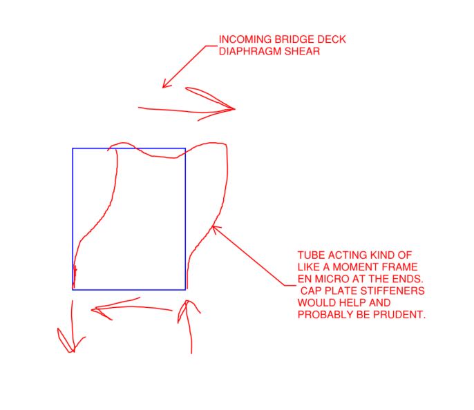
5) For the transfer of diaphragm forces, which I feel is what that code clause is speaking to, I think that you'd have to investigate a sidesway mechanism as shown below. Adding cap plates to the ends of the HSS would help.

6) I'm not a bridge guy and can't say definitively whether or not your average bridge engineer would be willing to forgo discrete diaphragm bracing in the HSS case.

C01_bhkczb.jpg
 
KootK said:
BA[/color]]4) The continuity is usually imperfect, even with the stiffeners, owing to the flexibility in the cap plate, beam flange, and bolts.
Imperfect perhaps, but the cap plate can be made as stiff as you wish.​
5) I feel that it is more accurate to say that the stiffener detail greatly improves rollover but does not necessarily make it impossible, at least not without quantification. No argument there.

6) To this day, and after decades of seeing the issue discussed here and out in the wild, I've not seen anyone put forth a robust calculation method for evaluating whether or not this detail is stiff and strong enough in any particular case. If you know how to do it, do tell.
Nothing to tell offhand, but I'll think about it.​

BA
 
I have been assuming so far, that the column braces the beam. It may be true that the beam braces the column or that both beam and column, acting together, resist any accidental lateral forces, but it would seem prudent to provide a somewhat stiffer column than a 3x3HSS.

BA
 
OP indicates that the column will be mounted on an existing foundation. That alone may limit the practicality of attempting a rotation restraining base connection there. Granted, flexural demand at the base many not be too onerous; it may well be that post installed anchors in unreinforced concrete can get the job done

BA said:
Imperfect perhaps, but the cap plate can be made as stiff as you wish.

BAretired said:
Nothing to tell offhand, but I'll think about it.

In the combination of those two statements lies the conundrum. Yes, the cap plate can be made as stiff as one wishes. But, then, what use is that if nobody knows how to figure out how stiff is stiff enough? Something like this probably wants to be a 3/8" - 1/2" cap plate if one care about the optics. More than 3/4" and I'm sure that there would be some explaining to do.
 
Kootk said:
1) I suspect that it would be a good deal stiffer than a bolted, beam over column detail.
What?? This seems like a bold statement. Maybe you could say equal. If you think about it you're bending a plate out of plane, or you are putting torsion on it which is kinda like bending it out of plane.

Kootk said:
I'm fine with the stiffeners business for coupling rotational beam end torsion to column weak axis flexure for the purpose of restraining beam end LTB.
So you are saying that both shear tab or beam over column with stiffeners would be fine to brace the beam end against twist and thus satisfy the definition of an LTB restraint and then we are just arguing if a shear tab or beam over column with stiffeners provides stiffer restraint, is that correct?


RFreund said:
What?? This seems like a bold statement. Maybe you could say equal. If you think about it you're bending a plate out of plane, or you are putting torsion on it which is kinda like bending it out of plane.

I stand by my original statement although, I suppose, one might have to FEM model both options to quantify it accurately one way or another. In my mind, a bolted and pretensioned shear tab is effectively a continuation of the beam web straight to the column face as far as torsional stiffness goes. With the beam over column connection, you've got all those sources of flexibility that I mentioned earlier:

KootK said:
The continuity is usually imperfect, even with the stiffeners, owing to the flexibility in the cap plate, beam flange, and bolts.

That's a fair bit of "stuff". And, like I said, most of our common, simple shear connections provide torsional restraint through the web rather than the flanges. So there's plenty of precedent for this.

RFreund said:
..then we are just arguing if a shear tab or beam over column with stiffeners provides stiffer restraint, is that correct?

That is substantially correct, yes. When it comes to torsional restraint in simple shear connections, I've always considered the full depth shear tab / single angle / double angle connections to be the gold standard and the beam over column with stiffeners to be the distant runner up. With regard to the beam over column detail, in my opinion:

1) There are proportions at which there is no way that it works. A W36 over an HSS3x3 for example, not that any decent engineer would actually do that.

2) There's nothing in the North American standards that directly implies that this detail is okay without evaluating its stiffness. And, as far as I can tell, nobody knows how to evaluate its stiffness.

Frankly, I've been astonished to find out that others feel differently about which of these connection typologies is better in this regard. And that's marvelous as it means that I stand to learn something here.

Anecdotally, there have been plenty of threads here where folks have been concerned about beam over column rollover and the proposed solution (not mine) has been to connect to the side of the column rather than run over top of it. So, while it is not apparent in this thread so far, I'm pretty confident that I'm not the only engineer out there that feels this way.
 
I note that there is some precedent for beam over column connections in the literature pertaining to Gerber systems.
 
@Kootk - OK, all fair statements.

Kootk said:
Anecdotally, there have been plenty of threads here where folks have been concerned about beam over column rollover and the proposed solution (not mine) has been to connect to the side of the column rather than run over top of it. So, while it is not apparent in this thread so far, I'm pretty confident that I'm not the only engineer out there that feels this way.

I have started one of these threads in the past, but it was for a case where there were no stiffeners or kickers. I will look back at my conversation with Mr (Dr. maybe?) Muir as he provided some pretty good information for this (also related to Gerber system). However, I believe we both concluded that there are lots of parts that contribute the flexibility of the connection, and they are all difficult to quantify, which is exactly what you are saying here.

Kootk said:
2) There's nothing in the North American standards that directly implies that this detail is okay without evaluating its stiffness. And, as far as I can tell, nobody knows how to evaluate its stiffness.
Ehh, kinda. If you look AISC manual section 2 around page 18 or 20 depending on edition. They say "Alternatively, the required stability can be provided with stiffeners in the beam web along with a moment connection between the column top and beam bottom to maintain alignment of the beam/column assembly. A cap plate of reasonable proportions and four bolts will normally suffice." They do go on to say that in "atypical framing situation.... Appendix 6 can be applied for both the beam and column....". They make it sound so friendly and easy in that last part.


Status
Not open for further replies.

Part and Inventory Search

Sponsor