Continue to Site

Eng-Tips is the largest engineering community on the Internet

Intelligent Work Forums for Engineering Professionals

  • Congratulations KootK on being selected by the Eng-Tips community for having the most helpful posts in the forums last week. Way to Go!

No lateral support at the supports of a beam 5

Status
Not open for further replies.

Logan82

Structural
May 5, 2021
212
Hi,

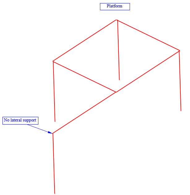
I have a situation where it is not possible to have lateral supports at one beam support of a platform. Normally it is standard practice to have lateral supports. Are there some reduction factors to apply to the resistance of this beam due to the non laterally supported beam support? There should be no torsion applied on the beam.
4_urx7gq.png
 
Replies continue below

Recommended for you

Thanks for the AISC stuff Rfreund. That's a worthwhile addition to the discussion for sure. I'm not so much anti stiffener and cap plate as I am pro shear tab
 
Putting aside the column head rotation which is an issue for web cleat as well as beam-over, this situation has been called 'beam on seat' or 'distortional buckling' in some papers. I've never seen the stiffener case discussed, but it may be possible to adapt the unstiffened equations to suit.

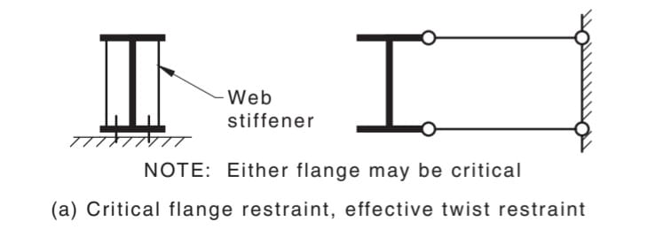
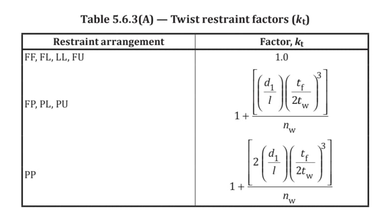
Here's the Australian/NZ treatment. The effective length is increased by the factor k_t (twist factor). n_w = number of webs. FP means only one end has btm restraint w/o stiffeners. PP means both ends. Australian engineers wouldn't think twice for stiffened because it's in the code itself as restrained.

20210712_194749_rsls3k.jpg


Screenshot_20210712-194256_Box_v5eibf.jpg


I'll see if I have any articles with background.
 
Maximum shear stress in a shear tab under torsion is approximately: Mt/bc[sup]2[/sup]*(3 + 1.8 c/b)
where Mt is the torsional moment, b is the long side and c is the short side

A W250x33 with a 10k reaction could have a shear tab of 6"x1/4"
Direct Shear stress = 10,000/ 1.5 = 6,667 psi

Maximum torsional shear stress = Mt/6*0.25^2 * (3 + 1.8*0.25/6) = 8.2Mt
If Mt = 1000'# (12,000"#), the torsional shear stress = 98,400 psi

KootK said:
1) I suspect that it would be a good deal stiffer than a bolted, beam over column detail.

I suspect it would be a good deal more flexible than a bolted, beam over column detail.
Unit rotation θ = 3Mt/bc^3G.


BA
 
I think it is time I pull out some FEA buckling analysis. Though I do wish the OP would fully flesh out the scenario. I'll make some assumptions where suitable.

steveh49 said:
Here's the Australian/NZ treatment. The effective length is increased by the factor k_t (twist factor). n_w = number of webs. FP means only one end has btm restraint w/o stiffeners. PP means both ends. Australian engineers wouldn't think twice for stiffened because it's in the code itself as restrained.
I'm an Australian engineer and I certainly WOULD think twice and thrice about the proposed setup.

The Australian code as far as LTB goes has plenty of holes and is far from perfect in its approach. It is too conservative in some aspects and not conservative enough in other aspects. But it seems functional enough and I haven't delved enough into other codes to know how it compares. But I certainly am aware of many areas that it doesn't address adequately. Not to mention the fact that there is no effective lateral restraint of the beam at this connection.

As far as the debate about which is more flexible a web cleat or a bolted and stiffened end plate. Throw enough steel and bolts at both options and you should get a stiff enough connection that the connection stiffness becomes negligible compare to the column/beam stiffness. Though a web cleat will never engage the flanges of the beam so it can never achieve the same stiffness that could be achieved with a stiffened seat.
 
Human, I meant the case illustrated in the standard where the beam with stiffened web sits on something decent, compared to a web cleat also connected to something decent. If the column is as stiff as a pile of jelly as seems to be the case here, stiffened web vs web cleat isn't going to make a difference.

Here's the most relevant paper in my collection.


BAretired said:
I suspect it would be a good deal more flexible than a bolted, beam over column detail.

I have two beefs with your latest argument BA:

1) You seem to be drawing conclusions about the relative stiffness of two details by numerically evaluating only one of them. I don't see the logic in that. In my mind, it's a bit like this argument:

a) KootK can run an ten minute mile.

b) We don't know how fast BAretired can run.

c) Clearly BAretired can run faster than KootK.

2) The form of your equations suggest to me that they consider St. Venant torsion but not warping torsion. If that's accurate, then your estimate will have neglected a significant source of rotational stiffness in shear tab connections, particularly for taller beams which would be the ones of greatest concern.
 
steveh49 said:
...this situation has been called 'beam on seat' or 'distortional buckling' in some papers.

In North America, I believe that we mostly know that phenomenon by the moniker "web side sway buckling". The general consensus, which I agree with, is that stiffeners effectively eliminate it.

steveh49 said:
Australian engineers wouldn't think twice for stiffened because it's in the code itself as restrained.

In practice, we don't think twice about it either. I save my concerns for my "sport engineering" endeavors, not the workaday crap. That said, it seems to me that the AU code provision that you've referenced has as its base assumption that the bottom of the beam has ideal, or nearly ideal, rotational restraint. And it's exactly the truthiness of that assumption that is now at issue here I believe.

steveh49 said:
If the column is as stiff as a pile of jelly as seems to be the case here, stiffened web vs web cleat isn't going to make a difference.

I certainly agree with that and that is why my design proposal would assume:

1) pin-pin column and;

2) the beam designed as a cantilever without the benefit of tip bracing, translational or rotational.
 
KootK said:
And it's exactly the truthiness of that assumption that is now at issue here I believe

I did understand what you were saying, so I'll explain my thoughts better. Web sidesway buckling has an approximately known effect, simplified as the k_t factor in Australia. That's based ultimately on web flexibility. If the stiffeners remove that flexibility, my suggestion was that a cap plate of the same flexibility would give similar capacity reduction. So you would set your reduction to what you could tolerate and back-calculate from the corresponding web stiffness.

However I think the article I posted goes there more directly, with the bonus of actual testing.
 
human909 said:
I think it is time I pull out some FEA buckling analysis.

I'll do my best to support your efforts in that but, for me, such an analysis is unnecessary. I take it as self evident that:

1) There are some proportions at which a shear tab would be stiffer. Namely, the tall beam, narrow column situations that would concern most engineers.

2) There are some proportions at which the stiffeners and cap plate would be stiffer. Namely, squat beams on wide columns that would concern few engineers.

I'll attempt to justify this stance below. Also, along similar lines of thinking, I would prefer to see you study a situation other than OP's situation. I feel that a more aggressive setup would provide us with more valuable insights. Maybe a W18x35 on an HSS4x4 post. You know the drill from previous threads: it goes better when we model a setup that we all agree is meaningful.

huma909 said:
Though a web cleat will never engage the flanges of the beam so it can never achieve the same stiffness that could be achieved with a stiffened seat.

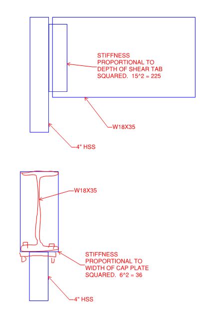
I would certainly support that argument IF it were a welded connection and the beam stiffeners landed right on top of column flanges. For bolted connections, I'm not convinced. Rather, I propose that the stiffness of the connection varies roughly with the square of the connection depth. So, in the scenarios considered here that means, approximately: depth of shear tab vs width of cap plate. And that won't be too far off from the depth of the beam vs the width of the beam.

C01_qidtfy.jpg
 
KootK, as a courtesy after what happened in our column discussion recently, I'll point out that I edited my previous post after you posted your latest, so you may not have seen the final version.
 
steveh49 said:
If the stiffeners remove that flexibility, my suggestion was that a cap plate of the same flexibility would give similar capacity reduction. So you would set your reduction to what you could tolerate and back-calculate from the corresponding web stiffness.

Sure, that makes perfect sense. Unfortunately, it still leaves us with the onerous task of trying to figure out just how stiff a cap plate connection actually is. And, if I had that value in hand somehow, I'd probably just make a B-Line for AISC appendix 6 as that would allow me to incorporate the column head rotation as well.
 
So is it the case that you just don't trust the cap connection based on instinct? Because it seems that the stiffness of the web cleat is also unknown.

Our standardised web cleat connection is an 8mm or 10mm plate with snug tight bolts. Is that similar to yours?
 
steveh49 said:
Our standardised web cleat connection is an 8mm or 10mm plate with snug tight bolts. Is that similar to yours?

Yup. I was originally thinking pretensioned bolts but, now that you mention it, I think that snug tight is probably right.

steveh49 said:
So is it the case that you just don't trust the cap connection based on instinct?

Yes to the mistrust but, as I mentioned previously, it is less that I am anti-cap plate and more that I am pro-shear tab when proportions are such that I'd be concerned about rollover.

Sort of on the "instinct" part. My instincts certainly come into play on this but there's more to it than that I feel. I'll get into that below.

steveh49 said:
Because it seems that the stiffness of the web cleat is also unknown.

That is true... and annoying. That said, I do feel that there are reasons to like the shear tab connections that go beyond mere instinct:

1) I stand by my argument that the stiffness of the connection will be roughly proportional to the square of the connection depth. This isn't the same as truly knowing the stiffnesses, of course, but it's still math damn it.

2) The depth of precedent for simple shear connections being able to successfully restrain beam end rotation is truly significant. Most infill beams, in fact, derive their rotational end restraint from simple shear connections that are only required to be 0.6d or whatever. In contrast, the AISC manual dedicates no less than four pages of details describing how one ought to go about stabilizing beam over column connections. Why does AISC give that issue so much air time? Because beam over column has inherent stability issues.

3) Human909 previously made a point that a) I feel is significant and b) we've kind of glossed over for the most part. Connection stiffness issues aside, a shear tab actually reduces the beams very tendency to roll over by shifting upwards the location at which the reaction is delivered into the beam, at least to the shear center.

My example of a W18x35 on an HSS4x4 is quite common place in light frame construction where posts have to get buried in narrow stud walls. Whenever I see it, I think to myself "now there's somebody who may have overestimated the reasonable range of applicability of that detail. That would have been better done as a shear tab". Perhaps I'm alone in that.
 
KootK said:
You seem to be drawing conclusions about the relative stiffness of two details by numerically evaluating only one of them. I don't see the logic in that.

I evaluated only the shear tab which would typically be used for the beam in question. The cap plate and stiffener option could be designed to handle a torsional moment up to almost the full moment capacity of the column if so desired.

KootK said:
The form of your equations suggest to me that they consider St. Venant torsion but not warping torsion. If that's accurate, then your estimate will have neglected a significant source of rotational stiffness in shear tab connections, particularly for taller beams which would be the ones of greatest concern.

In this case, we are talking about a W250x33 according to Logan82. Please enlighten me about warping torsion. I do not believe it applies in this case.

The shear tab is meant to carry shear. It is almost useless for torsion and can't compare with the alternative. Not even close.

BA
 
BAretired said:
The cap plate and stiffener option could be designed to handle a torsional moment up to almost the full moment capacity of the column if so desired.

1) In my experience, nobody does that in practice.

2) I think that it would be quite difficult to do that without welding in many cases given a limited number of effective bolts and prying issues.

3) Developing the column flexural capacity isn't really the issue. What would be needed is to develop the full column flexural stiffness. And that's even more difficult to do than developing the strength capacity.

BAretired said:
Please enlighten me about warping torsion. I do not believe it applies in this case.

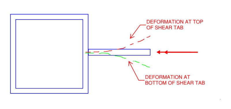
Sure, see the sketch below. Plane sections not remaining plane and all that jazz...

BAretired said:
It is almost useless for torsion and can't compare with the alternative. Not even close.

4) If it's torsionally useless, then how come so many simply supported / infill beams derive their torsional end restraint from just such simple shear connections?

5) I submit that shear tabs are a whole lot less torsionally useless once one accounts for the warping resistance mechanism.

C01_ydt1y3.jpg
 
Kootk said:
3) Human909 previously made a point that a) I feel is significant and b) we've kind of glossed over for the most part. Connection stiffness issues aside, a shear tab actually reduces the beams very tendency to roll over by shifting upwards the location at which the reaction is delivered into the beam, at least to the shear center.
I'd like to slightly hedge my statement there. IF the connection including stiffeners is 'fully stiff' up to the full moment capacity of the column AND the stiffness continues to the top of the beam then this affected would disappear. Which then brings us back to the stiffness of the connection argument.

But the second you have 'non negligible' flexibility on that seat the I would argue the effect would be quite significant. It a bottom beam support is a equivalently destabilising to a loaded top flange.
 
Human909 said:
I'm an Australian engineer and I certainly WOULD think twice and thrice about the proposed setup.

You would think twice about a stiffened bolted seat providing restraint generally? Or simply in this instance?
 
human909 said:
I'd like to slightly hedge my statement there. IF the connection including stiffeners is 'fully stiff' up to the full moment capacity of the column AND the stiffness continues to the top of the beam then this affected would disappear.

I hear 'ya. In my opinion, the description that you've described means welding for all intents and purposes.
 
It would be good to see some experimental results (or FE model) of the relative torsional stiffnesses of each type of connection, and the degree to which each will restrain torsional buckling.
 
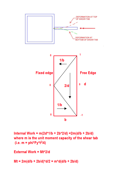
The factored strength of a 6"x3x1/4" shear tab with applied torsion is calculated below. Stiffness cannot be calculated using yield line theory.

The fixed edge and the two black dashed lines are assumed to be yield lines. The free edge is assumed to remain straight with zero moment. Relative deflection of +1 and -1 at top and bottom right hand corners are labeled on the sketch.

For a 6" x 3" x 1/4" with Fy = 50,000psi,
m = phi*Fy*t^2/4 = 0.9*50,000*0.25^2/4 = 703"#/"

Mt(factored) = m*d(d/b + 2b/d) = 703*6(6/3 + 6/6) = 12,656"# or about 1.05'k

image_dmwo8x.png


BA
 
Status
Not open for further replies.

Part and Inventory Search

Sponsor