Continue to Site

Eng-Tips is the largest engineering community on the Internet

Intelligent Work Forums for Engineering Professionals

  • Congratulations KootK on being selected by the Eng-Tips community for having the most helpful posts in the forums last week. Way to Go!

No lateral support at the supports of a beam 5

Status
Not open for further replies.

Logan82

Structural
May 5, 2021
212
Hi,

I have a situation where it is not possible to have lateral supports at one beam support of a platform. Normally it is standard practice to have lateral supports. Are there some reduction factors to apply to the resistance of this beam due to the non laterally supported beam support? There should be no torsion applied on the beam.
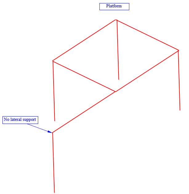
4_urx7gq.png
 
Replies continue below

Recommended for you

Human909 said:
the AS4100 LTB approach is a pile of horse shit

There are some oddities but I don’t know if I’d go that far!
 
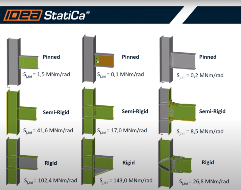
So in this example, the beam on top of the column with stiffeners would be more stiff for torsion than the beam connected to the column with a shear tab if I understand the results correctly. I have found this slide from a Idea-StatiCa tutorial indicating several variants of a connection with their respective Sji.
12_op2omk.png


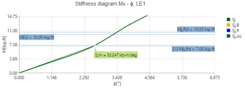
Does anyone have a ressource to learn more on how to interpret such stiffness diagrams in more detail?
2021-07-17_21_24_03-Rotational_Stiffness.pdf_bozjha.png
 
Said engineer came back with a simple, heavy but effective design but none of the beams had ANY restraint on the compression flange. I queried him on it and is response was pretty much along the lines of "the AS4100 LTB approach is a pile of horse shit".

What's his argument? AS 4100 is too complex and he prefers simple and conservative?
 
steveh49 said:
What's his argument? AS 4100 is too complex and he prefers simple and conservative?
I'm glad you asked.

The opposite. He is significantly LESS conservative. He wasn't worried about LTB at all because in his words "the tension flange" is fully restrained and that he has read research saying that is fully sufficient to prevent LTB!

Now to fill in a few blanks here. I had already run FEA buckling analysis and determined that buckling wasn't a concern. However I asked the question of him specifically because it clearly was inadequate according to AS4100 as an unrestrained compression flange would significantly reduce the beam's capacity as per AS4100.

Furthermore in this case beam is being loaded with a high UDL along the tension flange so the position of the load has a tendency to reduce the likelihood of LTB. Though the engineer didn't explicitly say this was part of his determination.

He is an old school engineer of pencil and paper and a huge wealth of experience and a regular expert witness when things go wrong. So he is a confident engineer with an excellent reputation.


IMO a good engineer follows the codes as a minimum. A GREAT engineer considers the codes as a guide and has the confidence to ignore the code when it is unsuitable or not applicable to particular circumstance.
 
Why was it considered a heavy design if it's less conservative?

If there's twist restraint at the tension flange, that would be continuous partial restraint. Is that the situation? Not sure that's bulletproof as trough girders need temporary bracing before the bridge deck closes the box, but then they aren't laterally restrained full span.

AS4100 gives the benefit for bottom flange loading in an appendix.
 
steveh49 said:
Why was it considered a heavy design if it's less conservative?
As I'm sure you are aware not all heavy things are more conservative and not all lighter designs are less conservative. This particular approach was literally heavy. It used heavy members rather than adopting lighter members.

steveh49 said:
If there's twist restraint at the tension flange, that would be continuous partial restraint.
The restrain wouldn't fall into my category of twist restraint. But AS4100 effectively leaves that as subjective. Which is my big hang-up.

Regardless even without twist restraint the member doesn't exhibit buckling behaviour before yield as confirmed by computational methods.

steveh49 said:
Is that the situation? Not sure that's bulletproof as trough girders need temporary bracing before the bridge deck closes the box, but then they aren't laterally restrained full span.
Sorry I should have mentioned that the comment he made was referring to readily available AU hot rolled members.

steveh49 said:
AS4100 gives the benefit for bottom flange loading in an appendix.
I was not aware of that. Thanks.
 
I'm still not sure what you mean by heavy here. Heavy loads and long spans generally need heavy structure - no further comment. Or is it something like going for UC sections instead of UB? That's a well-worn path to reduce bracing requirements.

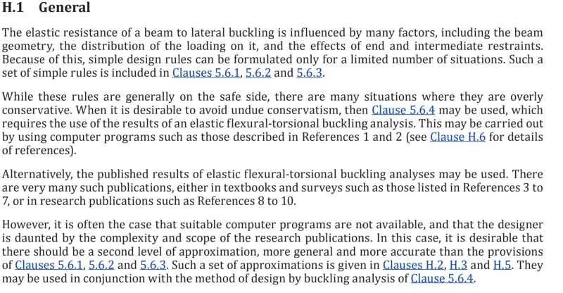
In terms of AS4100's LTB rules, I suspect you're expecting too much from such simple rules. This is from the code itself:

Screenshot_20210718-214935_Box_p0qcmu.jpg


You did computer buckling analysis, which is one of the AS4100 approaches. I suspect the other engineer is relying on published bucking analysis results - also part of the AS4100 toolkit.

Appendix H has some guidance on torsion restraint stiffness, but it's still only an approximation as per the H.1 comments (and the approx equal sign in equations of section H5.1).
 
He wasn't worried about LTB at all because in his words "the tension flange" is fully restrained and that he has read research saying that is fully sufficient to prevent LTB!...The restrain wouldn't fall into my category of twist restraint...the comment he made was referring to readily available AU hot rolled members.

I just put this into the Steel Construction Institute's Mcr software which I've been meaning to try. First time user so definitely potential for user error. However, the results were:

[ul]
[li]610UB101 (British version of it) spanning 12m.[/li]
[li]Lateral & twist restraint at supports[/li]
[li]Continuous lateral restraint of the bottom flange (no twist restraint) vs no restraint there[/li]
[/ul]

[ul]
[li]3% improvement for top flange load[/li]
[li]13% improvement for shear centre load[/li]
[li]52% improvement for bottom flange load[/li]
[li]Bottom flange load with the continuous restraint achieved elastic critical moment 52% of plastic moment.[/li]
[/ul]

If correct, the research must have included some twist restraint stiffness at the bottom flange so that Mcr >> Mp to achieve design capacity of Mp. For continuous full twist restraint, the software gave Mcr > 1000*Mp.


Yes lateral flange bracing of bottom flange alone shouldn’t do a whole lot for you, but if you restrain twist then that’s another story.
 
Think this is getting a bit side tracked but I take umbrage regarding some of the comments of the so called expert. There are very few Australian engineers with suitable knowledge of both pressure equipment and structural design to make such a call. The late Trahair who was one of the principal authors of AS4100 did significant research in the area of LTB. No code is intended to be a design guide or cover every scenario but the methods work quite well for normal construction.

Given the heavy design and the description supplied, I would say the PV engineer doesn't have suitable structural experience.
 
Status
Not open for further replies.

Part and Inventory Search

Sponsor