Continue to Site

Eng-Tips is the largest engineering community on the Internet

Intelligent Work Forums for Engineering Professionals

  • Congratulations KootK on being selected by the Eng-Tips community for having the most helpful posts in the forums last week. Way to Go!

No lateral support at the supports of a beam 5

Status
Not open for further replies.

Logan82

Structural
May 5, 2021
212
Hi,

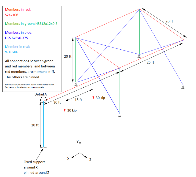
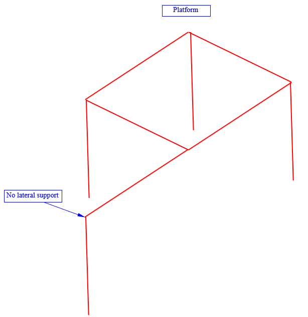
I have a situation where it is not possible to have lateral supports at one beam support of a platform. Normally it is standard practice to have lateral supports. Are there some reduction factors to apply to the resistance of this beam due to the non laterally supported beam support? There should be no torsion applied on the beam.
4_urx7gq.png
 
Replies continue below

Recommended for you

Thank you for your advices. Originally, I used a preliminary brainstorm idea for a small platform to build this question on this forum. I initially saw that as a more general question of design principle, rather than a specific problem to solve. It was a question that I had for some time.

I agree that in the example provided the column is too small. My intent in my project was to aim for a more standard platform, with lateral supports and bracings. I have found work arounds to make it work.

By the way, which software do you use to check the stiffness by FEA?

I was impressed by all the posts this discussion brought.

Thank you for the Twist restraint factors steveh49! By the way I tried to open your paper but the download did not work.
 
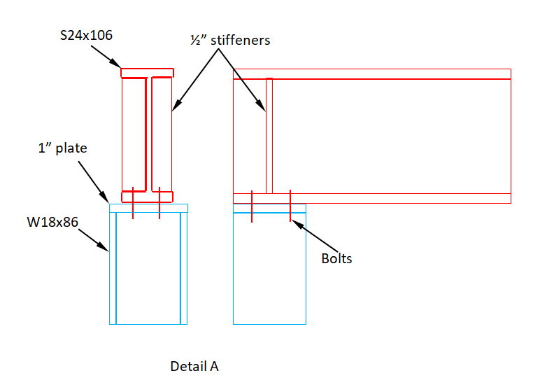
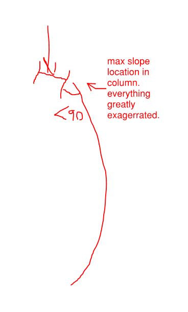
To answer the demand for more details, here is another example of a beam over a column, with more detail this time, that I sketched in case anyone would be interested to perform FEA. Note: I sketched this quickly and did not calculate the members yet.

9_qyvoxd.png


7_tlyfmp.png
 
W18x86 huh? That's darn near a shear wall. Just kidding, the height of this is about twice what I'd originally envisioned and I see that the load to that post has at least tripled. And the column kind of is doing the job of a shear wall here.
 
I suggest extending the column up, losing the bolts and stiffeners, and connecting the beam to the column web.

BA
 
BAretired said:
I suggest extending the column up, losing the bolts and stiffeners, and connecting the beam to the column web.

I agree, of course, but what's informed your decision to recommend that detailing now that the situation's a bit different than we had originally imagined?
 
KootK,

It just makes sense with the current members, whereas it didn't make sense with the previous members, or did it?
Actually, extending the HSS column and connecting the beam to the column was probably a better detail in the previous case as well, perhaps with something a little stiffer than a shear tab.


BA
 
BAretired, what do you have in mind by a connection "stiffer than a shear tab"?
 
@BA: thanks for the explanation. Also, your YLM skills are getting pretty bad ass even if the method doesn't speak to stiffness.

@Logan:

1) I'd push for a double angle connection if it fits. Given that it's a one off situation, nobody should get too excited about pushing for the economy of single angle clips which, if anything, might be less stiff than a shear tab. My gut feel is that a double clip angle connection would be stiffer than a shear tab connection. That said, please, nobody ask me to attempt to prove that.

2) A beam end plate welded to the beam flanges would be awesome for LTB stiffness. However:

a) probably more costly than other options.

b) probably less erection friendly than other options.

c) Doesn't accommodate tolerances well without shims.

d) Overkill in my opinion.
 
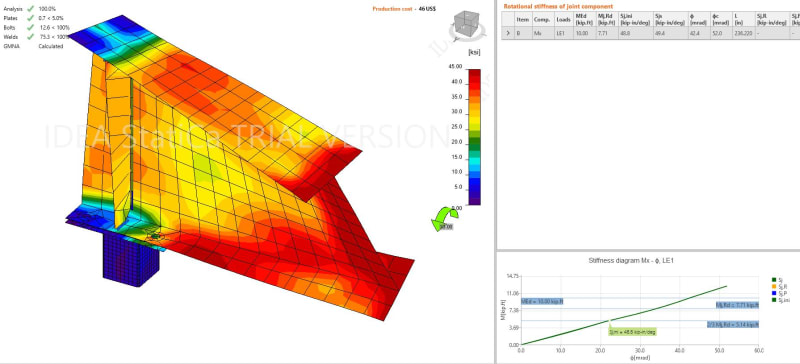
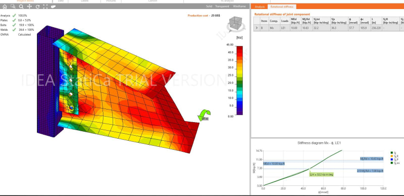
Here are some quick Idea StatiCa results:

Column is HSS4x4x1/4
Beam is W18x35
Cap plate is 1/2" thick with 3/4"Ø bolts on 3.5"x7" pattern. Stiffeners are 3/8" thick centered on column
Shear tab is 1/4" thick (5) 3/4"Ø bolts at 3" O.C. Beam is 1/2" from column, shear tab is 4" wide with bolt line 2-1/2 from column face.
10 kip-ft of torsion is applied to beam.

cap_plate_rotation_uwnf4u.jpg


Shear_tab_rotation_pgzf7t.jpg
 
Nice, I get so jealous of you guys with idea statica to play with. So what are the early stage stiffness? I'm afraid that my eyes are no longer good enough to read the graphs.
 
Yeah, I didn't realize the picture would come in so poorly. Let me fix that - see attached pdf.
I'm actually using a trial version at the moment and am very new to the program, I figured this would be some good practice - hopefully I will be able to convince my employer it is worth the money.


 https://files.engineering.com/getfile.aspx?folder=67b0f910-5abb-4211-9193-0d14d53bc551&file=Rotational_Stiffness.pdf
So 32 kip-in/deg for the shear plate and 48 kip-in/deg for the cap plate.

In both cases, most of the flexibility appears to be coming from the warping of the beam end itself. Would it be a simple matter to shorten the beam element significantly or to add side plates to dial down the warping?

Although perhaps the dominance of the warping suggests that both solutions are good enough to force the governing LTB buckling mode to effectively reelect that of rotational restraint at each end.

Also, would it be possible to model an incoming shear of, say, 25% of the beam shear capacity coincident with the torque? I feel that may be important to the stability picture with this and that one of two things will happen to the cap plate connection:

1) P-Delta effects will, effectively, soften the connection or:

2) Joint prestressing will stiffen the connection.

One of those...

@human909: I apologize, I was wrong... this is interesting to model.
 
Logan82 said:
BAretired, what do you have in mind by a connection "stiffer than a shear tab"?

There are a number of possible choices. To begin with, I would not have selected a 76x76x9.5HSS, weighing 18.1 kg/m for the column. I don't think the height of column was mentioned, nor the unsupported length of the W250x33, but I might have been tempted to select a 127x127x4.8HSS, weighing 17.9 kg/m but having nearly 7 times the stiffness of the smaller column and nearly twice the moment capacity. It also offers the option of using a double angle connection, even though I suspect a single angle would likely suffice.

Another option is a Tee section with the flange welded to the HSS, or possibly even a heavy shear tab, say 10 or 12mm thick. But without specifying the thickness, the fabricator is likely to provide 4.8mm or 6.4mm thickness, then charge an arm and a leg in a Change Order.

BA
 
KootK said:
@BA: thanks for the explanation. Also, your YLM skills are getting pretty bad ass even if the method doesn't speak to stiffness.

Thanks KootK, I'll take "bad ass" as a compliment.

BA
 
I change my mind actually: I'd like to see the warping and beam length as it is but with the 25% capacity shear add.

Does IdeaStatica let you have more column length if you want? I wonder if the rotation at the column top would affect the effective joint stiffness at all (P-Delta).

C01_fyui0x.jpg
 
Nice results. I assumed the cleat would be a lot softer in torsion compared to the stiffened seat.

As Kootk notes most of the flexibility is coming from the beam itself. Any chance of modelling the connection stiffness more directly, Eg by using a tube like Kootk suggest?

That could be compared to the support stiffness vs buckling load results in Steveh49’s paper.
 
I wonder whether the column torsion stiffness is also relevant. The bottom flange of the beam appears to be ~fully restrained against plan rotation in the current cap plate configuration whereas the web cleat allows it to warp opposite the top flange.

Is 1/4" web cleat the dominant size in practice? Could 5/16" (like 8mm common in Aust) be used without raising eyebrows? It's probably something like cubed sensitivity.
 
Tomfh said:
You would think twice about a stiffened bolted seat providing restraint generally? Or simply in this instance?
More just this instance.

Personally I find the AS4100 guidance regarding LTB restraints disgustingly vague in the context of a code that is otherwise quite proscriptive in most aspects. It is so open to interpretation that it can readily lead the unwary sheep down dangerous paths or make the make more circumspect engineers agonise excessively over how a restraint should be catorgised. (I'd largely place myself in this category.)

The enlightened engineers (I'm trying to reach enlightenment) know that the AS4100 LTB approach is a pile of horse shit and go their own way when then feel like it.

I palmed off a difficult design to an extremely experienced external consultant recently, partly because of workload and partly because it was technically a very large pressure vessel and I didn't want my name on it. Said engineer came back with a simple, heavy but effective design but none of the beams had ANY restraint on the compression flange. I queried him on it and is response was pretty much along the lines of "the AS4100 LTB approach is a pile of horse shit".

Kootk said:
@human909: I apologize, I was wrong... this is interesting to model.
I'm taking that apology and putting it in my back pocket! That is worth more than a pink star! [lol]

(It has been a busy week for me and likely going to continue that way. So I might leave the modelling for others on this one.)
 
Status
Not open for further replies.

Part and Inventory Search

Sponsor