Continue to Site

Eng-Tips is the largest engineering community on the Internet

Intelligent Work Forums for Engineering Professionals

  • Congratulations cowski on being selected by the Eng-Tips community for having the most helpful posts in the forums last week. Way to Go!

Normal Stress in orthogonal Directions

Status
Not open for further replies.

cal91

Structural
Apr 18, 2016
294
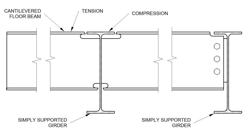
I have a case where there is a balcony which is supported from cantilevered steel floor beams. The floor beams tos are flush with their supporting girder steel beams. To provide continuity for the floor beams the flanges are CJP welded to the steel girder.

The top flange of the girder is in compression at the intersection with the floor beam (mid simple span). The top flange of the cantilevering floor beam is in tension.

I'm assuming I cannot have both the girder and floor beam both be at full capacity at the same location, and I can use Mohr's circle to understand what stresses are in the beam, but I'm not sure if there are any interaction provisions our design methods prescribed by AISC.

Any thoughts? Thanks in advance.

Capture_atvl3i.jpg


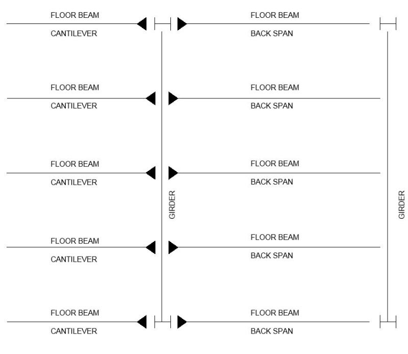
Edit: Here's the plan view.

Capture_xcmaxu.jpg
 
Replies continue below

Recommended for you

I would typically show the cantilever beam on the floor plan with a stipulated shear and moment and let the steel detailer look after the connection. The steel supplier will provide a design with the least cost to him.

Dik
 
Thanks, but my question in the mechanics involved rather than the connection detailing.

Edit: Specifically the top chord of the girder at that intersection. If it is at it's maximum compessive capacity in compression from the Girder, does that limit the amount of tension in the direction parallel to the floor beam.

For example, say it's 50 ksi material. If have it be in 45 ksi (0.9 * 50) compression, what is the maximum transverse tension that it could be in?

If I were to do this based on my own understanding of the mechanics, I'd find the maximum tension that will cause shear failure from Mohr's circle. Say it fails at 0.9*(0.6*50 ksi)=27 ksi. This would occur at only 9 ksi in transverse tension [45 - (-9) ] / 2 = 27 ksi.

 
not seeing why both members wouldn't be bending in the same direction.

why is the floor beam hogging while the cantilever is sagging ? isn't the down load applied to the floor, collected by the floor beam and given to the cantilever support beam ?

"The top flange of the girder is in compression at the intersection with the floor beam (mid simple span)." ok, but the sketch shows the cap of the floor beam is cut by the cantilever; so the cantilever is not mid-span, but between two short spans.

I'd consider your floor beams as short spans between the cantilevers, applying shear to the cantilevers.


another day in paradise, or is paradise one day closer ?
 
The floor beam, which is the cantilever, is "hogging" because it's a cantilevered out at the left. The girder, which is not the cantilever, is "sagging" because it is simply supported.

Hopefully the plan view helps

Capture_bztwfm.jpg
 
The interaction can be checked using the von Mises yield formula. It's not mentioned in the specification, but it is discussed in the Manual sections on connections. Blodgett discusses this connection in section 5.8 of Design of Welded Structures.
 
I'm skipping to solutions, but something I see in old bridges is to use a tie plate across the top rather than a weld -- if your geometry allows.

----
The name is a long story -- just call me Lo.
 
Cal91:
You will have a stress condition which is tough to justify, with that detail, if all the members can be at their max. stress at the same time. You will have some high principle stress conditions, two very high normal stress fields, both in the plane of the flgs.. If you were to run that framing system and detail through some FEA software, you would end up with a big red blotch in the immediate area of the intersection of the flanges and the ‘k’ areas of the members. Without knowing much more about the whole situation, loading conditions, member sizes, dimensions, why the top of beams must be the same elev., etc., etc. You guys just don’t seem to get it, but this type of info. helps experienced engineers get some early feeling for the magnitude of the problem. Why keep it a secret? Can you increase the size of the girder and beam, at least at the center beam line? Can you put a cover pl. over, but not welded to, the girder, which reduces the canti. flg. stresses and carries part of the moment over the girder? Can you lower that girder by a few inches, so the canti. flg. can pass over it? Can you change to two canti. and back span beam lines (not three) so that concentrated load and nasty crossed flgs. detial doesn’t occur at the middle of the girder? Can you put cover pls. on the girder flgs. to significantly reduce those flg. stresses? Then, finally, those crossed flg. details are a real bitch to weld (CJP or otherwise) without ending up with a really awful weld termination condition at the edges of the canti. and back span flgs., which also happen to be a reentrant corners.
 
For example, say it's 50 ksi material. If have it be in 45 ksi (0.9 * 50) compression, what is the maximum transverse tension that it could be in?

If 45 ksi is your design capacity, I'd be very cautious about having any tensile stress in the transverse direction. As Deker mentioned a few posts above, the von Mises criterion is commonly applied:

(f*x)^2 + (f*y)^2 - f*x.f*y + 3(v*)^2 < (phi.F)^2
where f* = normal stress (x & y are orthogonal directions); v* = shear stress; and phi.F = design capacity.

Since f*x and f*y are opposite signs (compression and tension), you can't max out one of them and still have stress in the transverse direction.


If I were to do this based on my own understanding of the mechanics, I'd find the maximum tension that will cause shear failure from Mohr's circle. Say it fails at 0.9*(0.6*50 ksi)=27 ksi. This would occur at only 9 ksi in transverse tension [45 - (-9) ] / 2 = 27 ksi.

I can't provide a reference for plates, but 27 ksi would be the shear capacity with a small normal stress. It reduces as the normal stress approaches yield stress as in this case.
 
to count the LH overhand as a cantilever you need to provide bending continuity, as someone suggested above, with straps joining the floor beam cap over the girder. To keep the upper surface flush, and to connect the lower caps, you may need tension end fittings, and bolt across the girder. As drawn you have a weld carrying shear and out-of-plane bending.

providing a dedicated loadpath like this (either straps or fittings) allows you to separate the tension stress from the cantilever from the compression stress of the girder. Note the RH floor beam isn't a true SS beam, it should be considered to be fixed at it's LH end (the RH end of the cantilever) ... it's more of a propped cantilever.

another day in paradise, or is paradise one day closer ?
 
Thanks for the answers everyone.

dhengr said:
You guys just don’t seem to get it, but this type of info. helps experienced engineers get some early feeling for the magnitude of the problem. Why keep it a secret?

Ignoring the jab, I "kept it a secret" because that information is irrevelant to my question. I was simply wondering about how one would calculate the capacity of this connection. If you would like to know the context, I work as an engineer for a steel construction company. This detail showed up in another engineering firm's contract drawings for a building that we are erecting. I didn't design this, I was just involved in some construction calculations for the building and this detail peaked my curiousity.

Regardless, I do appreciate the recommended alternatives you gave.
 
I have always been "on the fence" about this situation. A similar situation is when two open web steel joists are supported on opposite sides of a beam--the top flange of the beam is in compression due to overall bending along the beam, but the flange on each side of the web is a little cantilever perpendicular to the longitudinal axis of the beam, because it supports the joist seat.

I do not believe we are REQUIRED to check interaction of the stresses by code, perhaps because it typically seems to work, even if neglected.

However, I totally agree with the suggestion of using a tie plate--it is a better detail in my opinion (no von Mises stresses, no counting on a weld to hold up a cantilever, etc.).

DaveAtkins
 
if you're doing calcs, how does the weld stand up ?

another day in paradise, or is paradise one day closer ?
 
I'm not doing any calcs on the capacity of this connection, but the flanges are CJP welded.
 
so that gap (between the floor beam upper cap and the girder upper cap) is filled with weld ?

then it sounds like you have the combined stress state in the girder upper flange, as you suspected and maybe a von Mises check is warranted. and does the weld pass with tension loading ?

but "you guys" work with prescribed allowables (something like allowable bending stress is 60% ftu ?). does that protect your specific design ?

another day in paradise, or is paradise one day closer ?
 
For the specific case mentioned by DaveAtkins, a good solution can be found in the paper "The Performance and Design Checking of Chord-Angle Legs in Joist Girders" by Ted Galambos. The paper was published in AISC Engineering Journal, third quarter, 2001. The paper is free for AISC members. The procedure the author proposes can be extended to wide-flange beams. I sought out a solution when I had a wide-flange girder supporting long-span composite joists. The joist reactions were significant and the centroid of the reaction was located so as to cause transverse bending of the flange.
 
Status
Not open for further replies.

Part and Inventory Search

Sponsor