Continue to Site

Eng-Tips is the largest engineering community on the Internet

Intelligent Work Forums for Engineering Professionals

  • Congratulations waross on being selected by the Eng-Tips community for having the most helpful posts in the forums last week. Way to Go!

Offset rotation between Datums

Status
Not open for further replies.

edw.jack23

Industrial
Jun 22, 2022
8
Hi all,
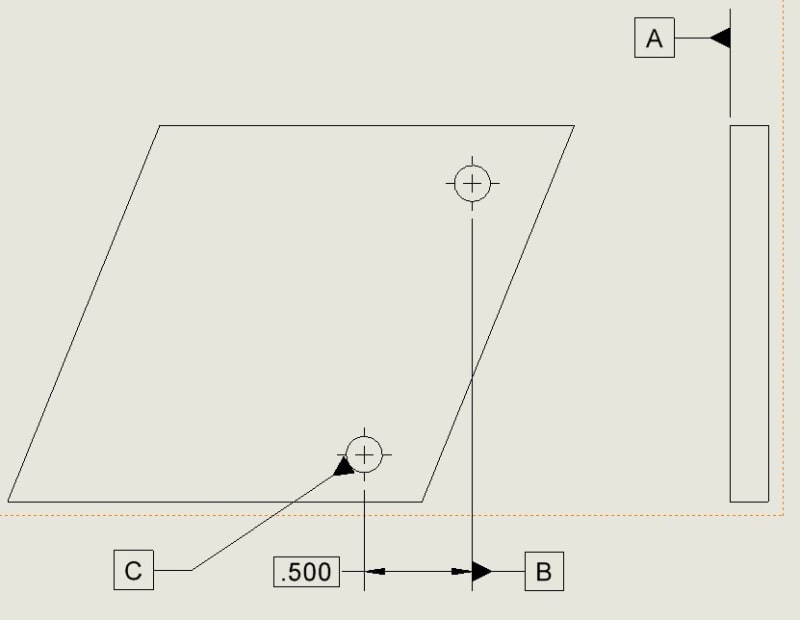
I want to know if there is a correct way to offset the rotation between two datum holes. See the attached drawing. Basically i want to measure both datums, but have the rotation between them offset to the specified basic distance. Is there a way to do that correctly per ASME? I couldn't find a specific example like this anywhere. Thanks!
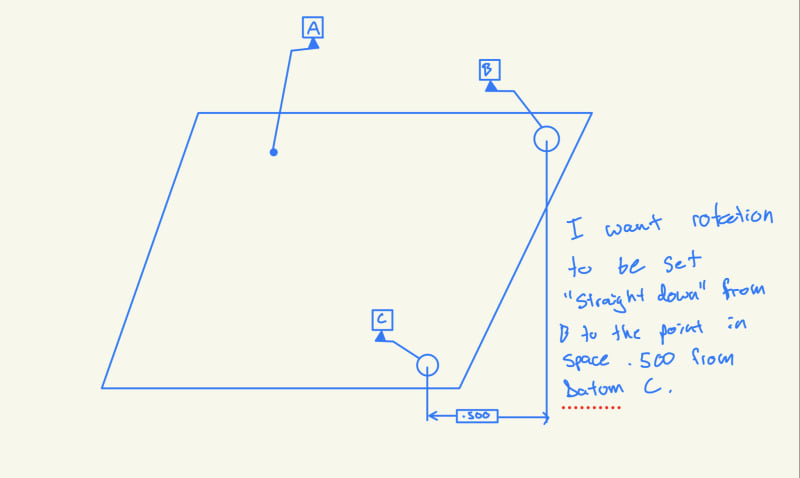
24-01-04_08-41-50_0043_sslxsf.jpg
 
Replies continue below

Recommended for you

Wouldn't the assumed rotation then be a straight line from B to C instead of normal to the drawing as shown?
 
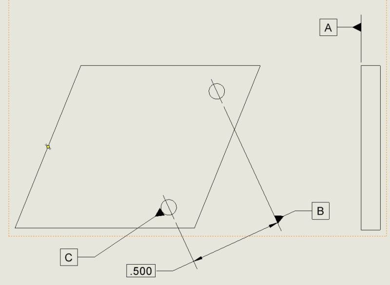
Would a basic angle solve it? Something like this so when measuring the offset is known?
24-01-04_10-56-48_0045_f8y36l.jpg
 
The whole notion of an assumed rotation is that you have a "horizon" already established. Unless you have B and C already toleranced so some other datums, I don't think the idea itself makes any sense (unless you're just trying for a visual look that aligns with the way the view is placed).

John-Paul Belanger
Certified Sr. GD&T Professional
Geometric Learning Systems
 
I am not understanding the idea of "straight down from B to a point in space .500 from datum C". What that does mean? Which FEATURE is .500 from "C"?
If there is no FEATURE then how the rotation is to be stopped?
Again, it is not clear what you are trying to achieve.
You might have something in your mind about your goals, but it is hard to convey at this point what exactly is the end game.
 
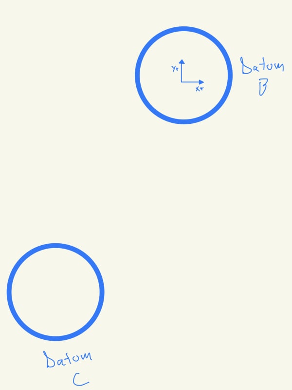
I guess I am having difficulty conveying it. I need to know if my interpretation of the datum reference in the very first drawing would be as shown here. If that is correct then I can explain what I want. If it isn't I need to know why. .
24-01-04_12-51-18_0049_nvytbw.jpg
 
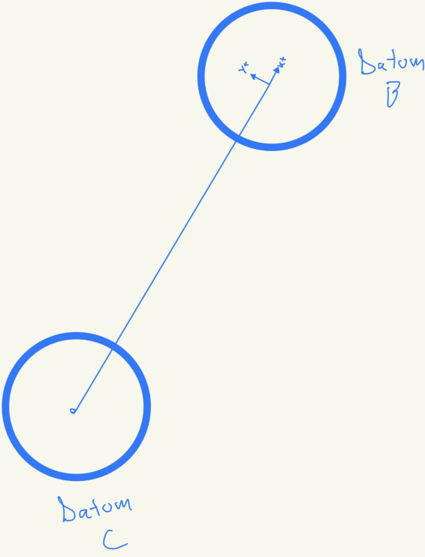
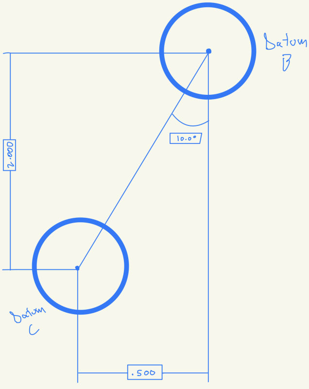
What I want is for it to be measured like this, but I don't know what I need on the drawing to convey that.
24-01-04_12-48-11_0048_rfxmhx.jpg
 
What is the order of precedence? I am assuming it is A|B|C|, right? If yes, then fig 7-6/ Y14.5-2018 on how to find the DRF could be used.
Figure 7-6 Development of a Datum Reference Frame
The coordinate system X,Y,Z is also shown.

 
OP said:
What I want is for it to be measured like this..............

You might not want to use then C as tertiary, but use other features which is aligned to the way you want to measure......
 
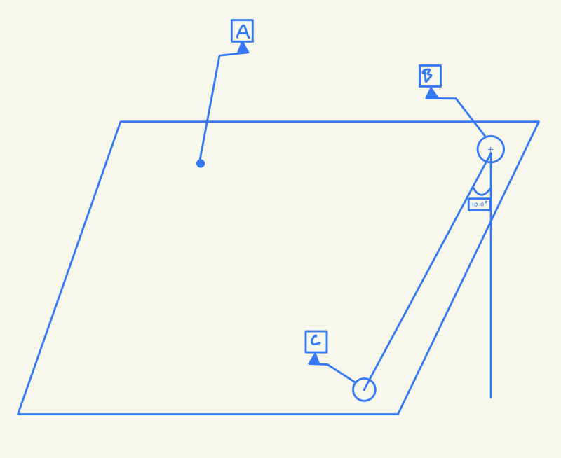
Assuming A|B|C precedence, do you think that this drawing would convey I want my XY origin centered at Datum B, and my datum axis to be offset by 10° from Datum C? The reason I ask is because a customer has a similar situation where measuring in a straight line from B to C is wrong, but measuring offset is correct. I'm trying to suggest a redline that will convey their intent.
24-01-04_13-12-30_0050_cjchql.jpg
 
"Basic dimensions can be applied to any feature (even features that are not the considered feature or one of the datum features for that FCF) or even to things that are not features (imaginary intersection points out in space as in Fig. 4-7/ ASME Y14.5-2009). This does not cause any issue because the basic dimensions are not applied directly to the actual part geometry.

The datum feature references determine how the actual part gets lined up to the datum feature simulators - and hence how the datum reference frame and tolerance zones are established on the actual part."


From Evan J.


I would say Datum Reference Frame is entirely another discussion.
 
Status
Not open for further replies.

Part and Inventory Search

Sponsor