Continue to Site

Eng-Tips is the largest engineering community on the Internet

Intelligent Work Forums for Engineering Professionals

  • Congratulations KootK on being selected by the Eng-Tips community for having the most helpful posts in the forums last week. Way to Go!

Opal Tower - Sydney Australia 28

Status
Not open for further replies.

CivilEngAus

Civil/Environmental
Jun 8, 2014
47


This could be an interesting and developing story in Sydney Australia. A 34 storey near new residential apartment tower in Sydney has been evacuated this afternoon over fears it is in structural distress with cracking noises heard during the day and one or more cracks developing; emergency services are treating it as a major incident.

Given we already have some of the toughest building codes in the world (although little to no registration requirements for engineers) it will be interesting to see how this plays out and what the crack(s) looks like to cause such a major emergency response.
 
Replies continue below

Recommended for you

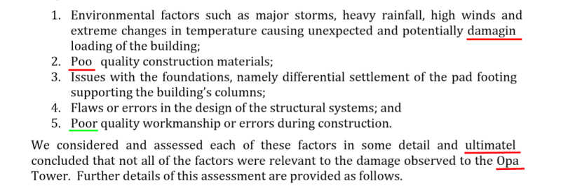
haha, sometimes you wonder if these things are proof read before going out...

Maybe its a problem with the PDF (I did try opening in adobe and bluebeam with the same result) or maybe its true, I suspect 'poor' was what they were after........ rather unfortunate potentially depending on what concrete tests throw up.

Capture_wowwk8.png
 
My first thought regarding the areas above the columns where the bearing failure/confinement failure has occurred:-

This hob beam is essentially a thin upstand wall, and as such there is zero confining reinforcement in the area directly above the column where the load is being dumped. (ties across the section would be expected in NZ, not sure in Australia what the requirement is, but gravity is the same). Very poor detailing for the transfer of loads into the columns.

The bit of the hob beam between the column is essentially not needed to carry the gravity loads, the bits over the columns below that are doing the work are required to act as columns, detailing it as a beam seems to be a fundamental error in appreciating how the loads are transferring form the panel above into the column below.

While there are dowels linking the hob beam to the column, seems to be very little reinforcement linking the hob beam to the column, guessing there will be tension/uplift here and a few stirrups seem to extend into the column but nothing more, you are presumable transferring a large force into a thin wall with no confinement. Dowels seem to have the hook/cog(?) turning at top of column into the slab so not tied/linked into the column (I'd expect to see some reasonable vertical reinforcement with horizontal confining links/stirrups extending down into the columns to lap with the column reinforcement, similarly in the bottom of the panel until the loads are spread out into the full wall width).

Plastic ducts seem like a poor detail, in NZ corrugated metal ducts are required. How is the bond or shear supposed to transfer through the soft plastic.

All in all the detailing observed in the photos seems quite poor based on my understanding of how they were using the walls as gravity walls, the report tends to read that the design was the first issue but is pretty light on details regarding this aspect. But still sounds like they are waiting for further information to flesh this aspect out.
 
Agent666 said:
haha, sometimes you wonder if these things are proof read before going out...
Yep. I noticed the same thing. Quite hilarious.

The report doesn't say too much in my brief perusing. I would really like to know the original design methodology. The need for the beam isn't obvious to me due to the stiffness of the wall. I'm surprised there hasn't been much comment on this. The beam doesn't seem to have failed as a 'beam' (from resisting moment), it seems to have failed due to bearing compression and shear. Can anybody shed some light on this?

To my mind there doesn't seem to be much sense in using a 500mm deep 'beam' as a 'beam' underneath a panel that is ~18m deep!

EDIT:

Agent666 said:
The bit of the hob beam between the column is essentially not needed to carry the gravity loads, the bits over the columns below that are doing the work are required to act as columns, detailing it as a beam seems to be a fundamental error in appreciating how the loads are transferring form the panel above into the column below.
Exactly what I am thinking. It seems to me they were assuming uniformly distributed load from the wall.
 
The report seems to be full of those spelling mistakes. But they got poor right once.
For a German reader, the Grandpa Tower (Opa Tower) doesn't make things easier to understand. Grandpa and turds. What happened?

Opa_Tower_report_spelling_errors_1_hzgoek.png


Gunnar Englund
--------------------------------------
Half full - Half empty? I don't mind. It's what in it that counts.
 
This

In-adequate tensile capacity in the horizontal direction in the bottom region of Panel A that rests on the hob beam spanning columns C21 and C38.

There is compelling evidence indicating that the wrong size reinforcing bars were placed in this area during manufacture of this particular panel  – 20 mm  diameter bars were used instead of 28 mm diameter bars (see  Figure8).

So :

It was either incorrectly manufactured or the wrong panel was used during construction or there should be columns C21 on L1-L3 and L10-L15 above and below unit 1005 and the initial failure point.
 
Human909 I suspect the upstand wall/hob beam is there due to the presence of the garden. Putting the joint lower would be a waterproofing issue. Yes agree the failure is via a compression mechanism vs bending mechanism.

Regarding the potentially wrong size horizontal bars, the way they phrase it, it sounds like these were a horizontal tie for carrying gravity load at base of the panel. I'm sure alternative strut and tie models could show this was adequate by using horizontal reinforcement further up the panel, really depends how it was designed in the first place I guess. Didn't sound like they were worried about the shear capacity (even 20 diameter bars would be unlikely for shear reinforcement typically).
 
A couple of things about the report of the three professors struck me. The first is their recommendation in several places in the report that the WSP design, both original and for rectification, should be "checked by an independent qualified structural engineering organisation". I assume by that the professors are not going to do that job.

We still haven't seen any structural drawings, including details of how the floor slabs, hob beams, precast walls, and cast in place columns interact. The report states that the professors have reviewed the design, but doesn't state to what detail.

Notwithstanding incomplete grouting issues, I am skeptical about the failures being primarily of a bearing/compression nature. Shortening of the floor slabs, shrinkage and post-tensioning induced, would be an issue I would want investigated, as the resulting restraint stress could well lead to some of the spalling which is shown in the photos.

 
So all the columns under align with the wall over?
 
Hokie66, I'd expect if it was predominantly due to the slab shrinkage (etc) that the damage would possibly be more localised at slab level and/or more cracking in the slabs? I have no doubt that it could contribute, but there didn't seem to be any slab damage at many locations, just wall damage including cracks going further up the walls. It could be that there was more slab damage, but on the basis of the pixelated photos its a bit hard to tell too much detail!

I guess at this stage we have more info (basically the photos, report didn't say too much apart from the reference/inference that the failure seems to stem from design issues). But as I see it we still don't have any concrete conclusions from the authors as I read it. I really hope the final report goes into a bit more technical detail, outlining loads, capacity, etc.

Regarding the "checked by an independent engineer" bit, checking the design is not part of their scope based on the outline in the report of the scope as I read it to.

Definitely it should be checked, but not only the remedial work, the whole thing should be checked and anything additional thats found should be addressed. During my peer review work often uncovering reasonably serious issues/omissions, I can tell you sometimes it didn't give you a lot of confidence that the people or persons that were capable of making these errors were the ones who basically had to determine and design the remedial design (at least in many situations you can lead them by the nose to something you could accept that would comply). Also, where there is one mistake, dig a little deeper and you often uncover more issues!

Interestingly on WSP's website they have been saying its been deemed structurally sound since 1st January, at least someone has confidence in their own design. Link

 
Tomfh said:
So all the columns under align with the wall over?

Seems so based on the plans that are marked up.

Wonder if there is any damage at the tops of the walls, as presumably a new column springs off the thin wall again at the top (sort of the upside down detail of the details that have failed)?
 
One thing I’ve been wondering - how would the slabs have been designed? Would it have been given to a D+C PT contractor?
 
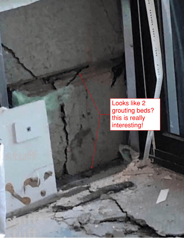
One question I still have and maybe it is a silly one.. Is there a second grout layer as pointed out by SheerForceEng? Certainly the description and the photos of the form-work indicate that there wouldn't be... Likewise with the commentary in the interim report. And it would be an odd detail.

But like I've said, I'm not really a concrete guy...

SheerForceEng's markedup photo:
interlan_photo_joz2py.png
 
Tomfh said:
One thing I’ve been wondering - how would the slabs have been designed? Would it have been given to a D+C PT contractor?

Yes, by APS, as stated on page 3 of the Interim Report:

Interim Report said:
The design of the post-tensioned concrete floors was carried out by Australasian Prestressing Services (APS).
 
Ingenuity, thanks.

That’ll be a very nasty fight.
 
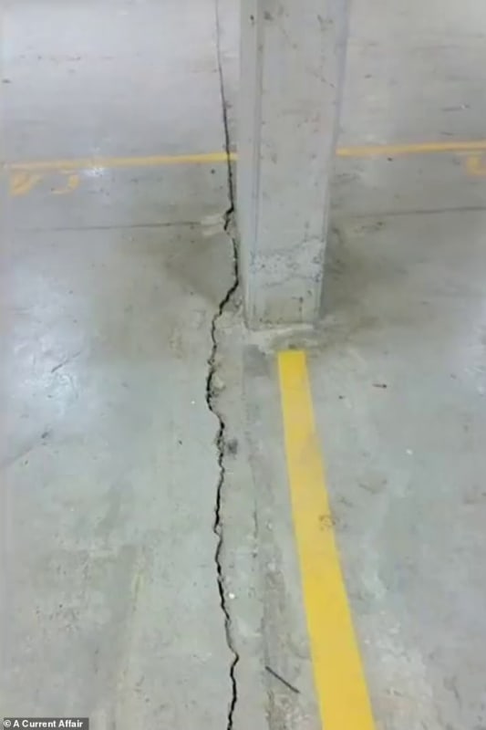
Hokie66, this article has a previously unseen picture of a floor crack in what looks like a carpark level. Not sure where it is, and they call them up as panel cracks so who knows, media can't tell if a wall is a floor and vice versa.

8507636-6590037-image-m-49_1547476908410_jgrmsi.jpg


Looks like a fairly wide crack if its a suspended slab.
 
It looks like a number of restraint shrinkage cracks I have seen in post-tensioned slabs without adequate crack control reinforcement.
 
Looks like a slab on grade to me with a badly detailed expansion joint. Looks like joints in both directions meeting at one corner of the column. Above the column, the crack follows the joint perfectly. Below it wanders off by 50mm or so.
 
Yes it looks like slab on grade. I’ve seen that a few times where the crack wanders off.

I’m not sure it’s a correct photo.
 
@Tomfh:
"I’m not sure it’s a correct photo."

The Unisearch report mentions "These activities have focused on various structural elements in sections of the building located on Levels 3, 4, 9, 10, 16 and 26, as well as the basement level B3", but there is no further discussion or photographs of the damage observed in basement B3. (Basement B3 is the bottom basement level, so it is very likely that this slab is constructed as a "slab on grade".)

I would assume they saw the floor slab crack shown in this photograph, and concluded that it was "minor damage" only, and not associated with the "major" structural issues in the upper floors.

 
Status
Not open for further replies.

Part and Inventory Search

Sponsor