Continue to Site

Eng-Tips is the largest engineering community on the Internet

Intelligent Work Forums for Engineering Professionals

  • Congratulations KootK on being selected by the Eng-Tips community for having the most helpful posts in the forums last week. Way to Go!

Orientation controls referencing 2 datums 2

Status
Not open for further replies.

Sem_D220

Mechanical
Jul 9, 2018
290
What are the opinions on the following schemes?

1. Angularity control referencing 2 datums in the FCF, when the basic angle is specified between the controlled face and the secondary datum. The primary and the secondary datums are perpendicular to each other.

2. Parallelism control referencing 2 datums in the FCF, when the controlled face is nominally parallel to the secondary datum and perpendicular to the primary datum.

3. Perpendicularity control referencing 2 datums in the FCF, when the controlled feature is nominally perpendicular to the secondary datum and at some other angle to the primary datum.

I haven't seen any of these brought as an example in the Y14.5 standard (unless I'm missing one), or in any other sources I was exposed to, but I also don't see how the contents of chapter 6 may reject those schemes. Schemes #1 and #2 are ones I wanted to implement for real cases, but hesitated (eventually I did :)). As for #3, I haven't encountered a case requiring this, but I can imagine one. I think I once heard a GD&T professional say that there should always be a basic implied 90° angle (for perpendicularity), or a basic angle of some other value (for angularity) between the controlled feature and the primary datum feature whereas the secondary datum may only constrain DOF / orient the tolerance zone. But, if the DRF should first and foremost reflect the functional interface, there certainly may be cases where a vice-versa scheme is justified. The problem is - there are no figures to point to if such position needs to be supported. In Y14.5, looking for orientation controls that reference more than one datum, I find only figures 6-4, 6-8, and even 6-17, all show an implied right angle relationship or basic angle between the controlled feature and the primary datum reference, never to the secondary.

Has anyone else dealt with this dilemma? Maybe it's only my lack of knowledge / experience, and such schemes are either commonly practiced or clearly not supported? Whatever the case is your input will be very much appreciated.

Edit: I'd like to add that I realize that one solution could be to use profile of a surface for orientation, but from various reasons I prefer to utilize orientation controls and reserve this solution only as a last resort, if needed.
 
Replies continue below

Recommended for you

The reference for parallelism is the datum plane, not the datum feature. That makes sense for the control since we want the controlled feature to be parallel to the face that should contact datum feature B. Yes, the fact that it is only contacted on 2 points by the secondary datum feature simulator makes the relationship between the datum feature and the datum less tight, but that does not reduce the meaning of "parallelism" the way it should be understood in this case.
In addition, if datum feature B is sufficiently validated for perpendicularity wrt datum A (like it's usually done in these cases), the relationship between datum feature B and the controlled face will not end up being "far from parallelism" if the parallelism as shown in the sketch will be within tolerance.
However, I accept the fact that it can be said that the "main" relationship required by the FCF shown is perpendicularity.

Parallelism to 2 datums can actually control both parallelism and perpendiculariy (or other angular relationship) of the controlled face to the datum references. The door was opened by fig. 6-4. Perpendiculariy or parallelism are not "pure" in a sense of controlling only 0°/90° relationships to the DRF.
 
Sem D220 said:
Fig. 6-4 clearly shows that there is no requirement from both datums in a FCF to have the basic angular relationship associated with the symbol to the controlled feature.
Also:
Parallelism to 2 datums can actually control both parallelism and perpendiculariy

No, it cannot. The standard is very clear, you always specify orientation wrt primary datum:

ASME Y14.5.1M said:
6.6.1 Planar Orientation Zone
(a)Definition. An orientation tolerance which is not preceded by the diameter symbol and which does not include the notation EACH ELEMENT or EACH RADIAL ELEMENT specifies that the toleranced surface, center plane, tangent plane, or axis must lie in a zone bounded by two parallel planes separated by the specified tolerance and [highlight #FCE94F]basically oriented to the primary datum[/highlight] and,if specified, to the secondary datum as well.

This is exactly what is wrong with your picture.


"For every expert there is an equal and opposite expert"
Arthur C. Clarke Profiles of the future

 
I'm glad this point was brought up because I'll be honest, I hadn't given much specific thought to this topic - I guess its something I sort of took for granted.

I have to say I agree with the majority on this thread, the only way to ensure total and complete unambiguous definition of a feature is to ensure the primary datum and datum precedence directly correlate to the type of orientation control specified. If as in your sketched example you are calling out parallelism but the primary datum is not parallel to the feature and is instead perpendicular, then it should probably be changed to perpendicularity. In fact, since the feature is nominally perpendicular to the primary datum in your sketch, I would almost argue that what you have actually done is call out perpendicularity in a very confusing fashion, despite using the parallelism symbol. I don't think thats a practical interpretation though - in reality I think you've created a situation where the parallelism control is "fighting" the datum precedence which suggests the feature should be first controlled nominally perpendicular to the primary datum.
 
I would also use the word "contradicting" instead of "fighting" in my previous post - the right word escaped me at the moment.

As an additional example and extension of the concept, take Figure 6-8. Because datum A is primary in the FCF it is interpreted to mean that the hole axis is to be controlled at 60deg to primary datum A and secondary datum B constrains the additional degree of freedom, NOT the other way around. If you keep everything the same but change the angle to 90deg the interpretation stays the same. Further if the basic angle shown is 90deg and the control is changed to perpendicularity, the interpretation stays the same. If now the basic angle shown is 90deg and the control is changed to parallelism I would say you have created a situation which is at best confusing - why would applying a parallelism control override the datum precedence?

If my understanding of this section is correct, I would think a good test of this would be whether you can replace the orientation symbol in the FCF with angularity (allowed per the standard - if there are any restrictions on this someone please let me know) and the meaning stays the same. I would say in your examples it does not, therefore they are not compliant.
 
semiond said:
TZ should be parallel to B and perpendicular to A. The part should make contact on 3 high points at datum feature A and 2 high points at datum feature B. With that description do you consider the scheme shown in the sketch correct or not?
Side note that might be relevant - for many cases of this type I encountered, parallelism to B is actually more important than perpendicularity to A. However, I do not consider it wise to break it down to two separate orientation segments (parallelism and perpendicularity) with different values, each referencing a single datum. That is because such scheme would not reflect the real application interface of the part. It will create 2 separate tolerance zones within which the face should be contained, and none of those TZs will be required to be oriented as I described above. It is important to orient the part for inspection as it functions in the assembly.


Semiond,
At this point I'm not sure if your objections are fully genuine or are just arguments for argument's sake.
Could you, please clarify your post?


CheckerHater,
Thanks for directing to the mathematical definitions standard, I haven't looked in this reference on this topic before.

However, the last sentence in the quote you provided states:"...and, if specified, to the secondary datum as well." I'm glad you didn't skip this last part. This is what I meant in the first quote you referred to. Even if we assume it's not intended, can you deny that the specification shown in fig. 6-4 controls parallelism to datum plane B? Can you deny that the tolerance zone is basically oriented to both the primary and secondary datum planes?

chez311, I agree that there is some problematicalness in my parallelism sketch. Also, I'm aware that if I change the tolerance zone to perpendicularity, the tolerance zone will stay exactly the same. The reason I wanted to specify it as parallelism in the real case is: The main concern was parallelism to the secondary datum plane, and perpendicularity to the primary is less important functionaly. But the part assembles in a way that corresponds to A|B| . If the callout was changed to perpendicularity with B as secondary, geometrically nothing would change. But then, even in the spirit of the opinions expressed in this thread, the communicated intent (not the geometrical meaning) would be that parallelism to B is more an outcome than a goal. Since unfortunately not all drawing users are as knowledgable at GD&T as the members of this forum, someone could simply ignore the secondary datum and only check perpendicularity to A ("this one is not supposed to be perpendicular, it must be a mistake"). And since the standard doesn't state that the normally parallel datum should always be the primary - I thought it would be OK to call out parallelism that way, and later do the explanations when questions are raised.
Again, I understand the objections and don't recommend to anyone duplicating that scheme. It was probably better to replace the parallelism symbol by that of angularity. However, I am yet to witness something that clearly indicates illegality. I would be glad to learn that the standards have a clear saying on this issue.
 
It said right there in the standard: "basically oriented to the primary datum and... to the secondary datum".
There is no need to deny the obvious. In the particular case on Fig. 6-4 it will control parallelism, with EACH ELEMENT added - not so much.
But we were talking about YOUR picture.
Do you agree that it makes no sense because controlled surface cannot be made parallel to primary feature A"?
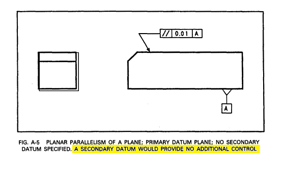
If you look at Para. 6.4 saying "If the primary datum feature alone does not constrain sufficient degrees of freedom, additional datum features may be specified" it's pretty clear that secondary datum is added "if necessary".
And guess what, it's not necessary according to the same book:
Fig._A-5_ijjqjc.png

This is why using secondary datum cannot be recommended as legal unambiguous way to add extra control.

"For every expert there is an equal and opposite expert"
Arthur C. Clarke Profiles of the future
 
chez311, I was writing my previous post while your post from 13:48 was submitted. I now see your reference to 6-8 and the angularity issue. Let me ask you this question: for the part at fig 6-8, there can be a rear face (hidden at the view) perpendicular to B and A. Let's call it datum fature C. As the hole shown, with basic angle to datum feature A, would you consider it right if the datums specified in the FCF were |C|A| ? (this is what I meant by scheme #1 in the opening post)

greenimi, I'm sorry if that's tge the impression you got, could you specify what are the points that should be further clarified in the quote?
 
CheckerHater, if we are talking about legality, I can relate to the reasoning, and the assumption that since the secondary datum is not mandatory, the nominally parallel datum should be the primary. I don't see how this is stated as an obligating rule, it's rather a common conclusion.
The end of para 6.4 talks solely about constraining degrees of freedom. It doesn't dictate what the orientation associated with the control must be relevant to the primary datum (Edit: obviously I'm talking about cases when more than one datum is referenced).
 
semiond,

I understand your point about communicated intent, but I don't see how that would translate into a measurable control. What I think you're trying to accomplish is some sort of gray area between indirectly controlling parallelism to a secondary datum with perpendicularity and directly controlling parallelism to a primary datum, by specifying a combination of orientation callout and DRF that contradict each other - this does not appear to be supported by the standard. I would actually say parallelism to [B|A] would pretty much accomplish that but you have suggested otherwise. EDIT: THIS IS IN REFERENCE TO YOUR SKETCH

Sem D220 said:
Let me ask you this question: for the part at fig 6-8, there can be a rear face (hidden at the view) perpendicular to B and A. Let's call it datum fature C. As the hole shown, with basic angle to datum feature A, would you consider it right if the datums specified in the FCF were |C|A| ? (this is what I meant by scheme #1 in the opening post)

If by "right" you mean legal - then yes, it doesn't matter how the basic dimensions are established. It would just mean that now the primary control is 0deg (parallelism) to your new datum C and datum A only serves to constrain additional DOF. I'm not sure how that affects anything I said previously. EDIT: THIS IS IN REFERENCE TO FIGURE 6-8

EDIT#2: Apologies for the multiple edits. I want to retract my statement about parallelism to [B|A] (ref strikethrough above) - I'm not so sure of that now. My other statements stand.
 
Sem D220 said:
I can relate to the reasoning, and the assumption that since the secondary datum is not mandatory, the nominally parallel datum should be the primary. I don't see how this is stated as an obligating rule, it's rather a common conclusion.

So basically you are saying that by calling out parallelism with a DRF where the primary datum is not parallel to the feature that it overrides the datum precedence? I would have to strongly disagree with you there. If your intent is for it to be controlled parallel to a certain datum, that datum should be primary (first in the DRF). Anything else is contradictory and ambiguous.
 
To all,

Sem D220 said:
Let me ask you this question: for the part at fig 6-8, there can be a rear face (hidden at the view) perpendicular to B and A. Let's call it datum fature C. As the hole shown, with basic angle to datum feature A, would you consider it right if the datums specified in the FCF were |C|A| ? (this is what I meant by scheme #1 in the opening post)

I have already said I thought the scheme presented in the above question would be acceptable. As an extension of this, would there be an issue in this theoretical case if parallelism was called out instead of angularity? It doesn't seem to me it would matter that it is not parallel to the secondary datum - just as in Figure 6-4 the feature is not perpendicular to the secondary datum. I am only asking because the only examples shown with parallelism, even of an axis, only feature single DRF's with a single datum.
 
Actually it's quite simple:

1. Angularity control referencing 2 datums in the FCF, when the basic angle is specified between the controlled face and the secondary datum. The primary and the secondary datums are perpendicular to each other. - WRONG. Basic angle must be specified between the controlled face and the primary datum

2. Parallelism control referencing 2 datums in the FCF, when the controlled face is nominally parallel to the secondary datum and perpendicular to the primary datum. - WRONG. The controlled face must be nominally parallel to the primary datum

3. Perpendicularity control referencing 2 datums in the FCF, when the controlled feature is nominally perpendicular to the secondary datum and at some other angle to the primary datum. - WRONG. The controlled face must be nominally perpendicular to the primary datum

I think I once heard a GD&T professional say that there should always be a basic implied 90° angle (for perpendicularity), or a basic angle of some other value (for angularity) between the controlled feature and the primary datum feature whereas the secondary datum may only constrain DOF / orient the tolerance zone. - He was correct. The tolerance zone always must be basically oriented to the primary datum

"For every expert there is an equal and opposite expert"
Arthur C. Clarke Profiles of the future

 
CH said:
1. Angularity control referencing 2 datums in the FCF, when the basic angle is specified between the controlled face and the secondary datum. The primary and the secondary datums are perpendicular to each other. - WRONG. Basic angle must be specified between the controlled face and the primary datum

Well, fig. 4-7 in Y14.5-2009 seems to disagree with that.

For what it is worth, I too believe that in case of perpendicularity and parallelism callout the symbol used in the FCF should match the relationship between primary datum and the toleranced feature, but that figure (4-7) is actually the one that can be used at any time by anyone, like semiond in this case, to say that this belief is just a personal preference with no solid support in the standard.
 
I place Fig. 4-7 next to Fig. 7-45 :)

I will always place mathematical definition above the picture.

And I have all the rights to do so, thanks to Para. 1.1.4:

"The figures in this Standard are intended only as illustrations"


"For every expert there is an equal and opposite expert"
Arthur C. Clarke Profiles of the future

 
How is 4-7 like 7-45?

Datums are always mutually perpendicular as shown in 4-7. 7-45 seems to be showing something completely different.

Also, 1.1.4 can only be used in certain cases. It's not a blanket justification for remaining in denial. For example, 3-29 is about feature control frame placement. That's all. Someone can't point to that figure and say that there's no need to control coaxial features because the location of the OD and the boss aren't controlled. Those issues aren't the point thus it's safe to say this figure is incomplete and 1.1.4 is in effect.

On the other hand, if someone believes that half dimensions must be used to indicate the location of a hole pattern around a datum centerplane and someone else refers to figure 4-7, you can't just claim 1.1.4 is in effect, because the title of that figure is literally "Positional Tolerancing at MMC Relative to Datum Feature Center Planes." That's exactly the point of that figure.

John Acosta, GDTP Senior Level
Manufacturing Engineering Tech
 
chez311 said:
So basically you are saying that by calling out parallelism with a DRF where the primary datum is not parallel to the feature that it overrides the datum precedence?

chez311,
If I understand the question correctly - definitely not. No datum precedence should be overriden. This is the most important thing. The whole point here is that I am trying to preserve the datum precedence order and the constrained degrees of freedom, as derived from the real application assembly. This is why I avoided from swapping the precedence order between datums A and B in the pralallism parallelism sketch embedded.

I asked you about the modified fig. 6-8, with the rear hidden face as datum feature C, with a purpose. like powerhound at the beginning of this thread, and unlike CH now, you agree that it is legal (and a similar scheme is shown in fig 4-7 as noted by pmarc). Now I add some more details: In it's functional assembly, the part is first put on the mounting base against datum feature C, then located to it's place and further oriented by datum feature A, and when stable, clamped firmly against datum feature C. The 60° basic angle to datum A is specified for a good reason and needs to be controlled. It is important functionally that there will be a 60° angle between the hole axis and the mating face which is represented by datum feature simulator A at inspection. Do you agree that in order to verify that angle, it would be reasonable to control angularity referencing datum C as primary, and datum A as secondary? This will no doubt also verify parallelism to C, as part of the angularity control. But the main goal is to verify the 60° angle.

If everything so far sounds reasonable, imagine that the 60° angle was changed to 0°, and the symbol was changed to parallelism. Would that control loose it's legitimacy in that case?
 
Sem D220 said:
the part is first put on the mounting base against datum feature C

Then C should be primary. This changes the scenario significantly. You still need to locate the hole with position. That determines where it will land in the assembly. Then refine for parallelism to C and also angularity to A if needed, or just refine with angularity alone to C and A.

John Acosta, GDTP Senior Level
Manufacturing Engineering Tech
 
CH, calling out the datums separately is not the same as calling them out as part of a DRF that represents the real assembly and the mounting method. There is a chance that angularity to A only and parallelism to C only will accept parts that wouldn't be accepted by angularity to |C|A, or vice-versa. In any case angularity referencing |C|A is a closer representation of reality in the scenario I described.
 
CH said:
I place Fig. 4-7 next to Fig. 7-45 smile

I will always place mathematical definition above the picture.

And I have all the rights to do so, thanks to Para. 1.1.4:

"The figures in this Standard are intended only as illustrations"

True. It is your choice to do so.

Not sure what mathematical definition you are exactly talking about, but it is interesting that in the standard for gages and fixtures Y14.43 from 2003 (so not even the newest one) the drawing of the gage used to verify position of the holes in the part from fig. 4-7 (fig. 4-4 in Y14.5M-1994) also uses angularity to control orientation of datum feature simulator C with respect to datums A and B. I do not think you will say that in that figure the angularity callout falls under "The figures in this Standard are intended only as illustrations" statement.
 
Status
Not open for further replies.

Part and Inventory Search

Sponsor