Continue to Site

Eng-Tips is the largest engineering community on the Internet

Intelligent Work Forums for Engineering Professionals

  • Congratulations KootK on being selected by the Eng-Tips community for having the most helpful posts in the forums last week. Way to Go!

OZ offest tolerance ZOne. ISO GPS 3

Status
Not open for further replies.

2020Learner

Automotive
Jun 27, 2021
19
hello Team,

Could you please explain me how to Interpret OZ (Unspecified Linear tolerance zone Offset (Offset Zone)modifier as per ISO GPS with example.
Any Sketch to Understand better way with Application wise
 
Replies continue below

Recommended for you

Hello cr7,

Yes i saw this video's, Difficult to understand because i dont know German language
 
2020Learner,

If you have access to the latest version of Y14.5 standard from 2018, take a look at the Dynamic Profile Tolerance Modifier paragraph (11.10). Conceptually, this and the ISO's OZ work the same.
 
Here is an example of profile tolerancing with OZ modifier.

2022-10-23_bqr52e.jpg


But, I have a question on this example, shall we add an UF modifier before the Between(K to L) symbol?

Season
 
Season,
Why you want to add UF? Are there multiple features between K and L or just one feature?
 
Please take a look at another example as highlighted

2022-10-23-1_kgqwk5.jpg


Season
 
Season,
Maybe UF is needed for features that go over 180° (degrees)...just saying.

So in your first attached case, why the syncronisation part is not needed? Or why has been omitted by your example from the standard?

pmarc,
Do you have any idea?


Maybe the first case posted by SeasonLee is meant to be one irregular curve with no constant radii that can be considered separately, whereas the other is two radii, R72 and R60, tangent to each other.
 
Burunduk,
If the first case posted is meant to show a single irregular surface, then I am not sure I see a reason for the use of the between notation.

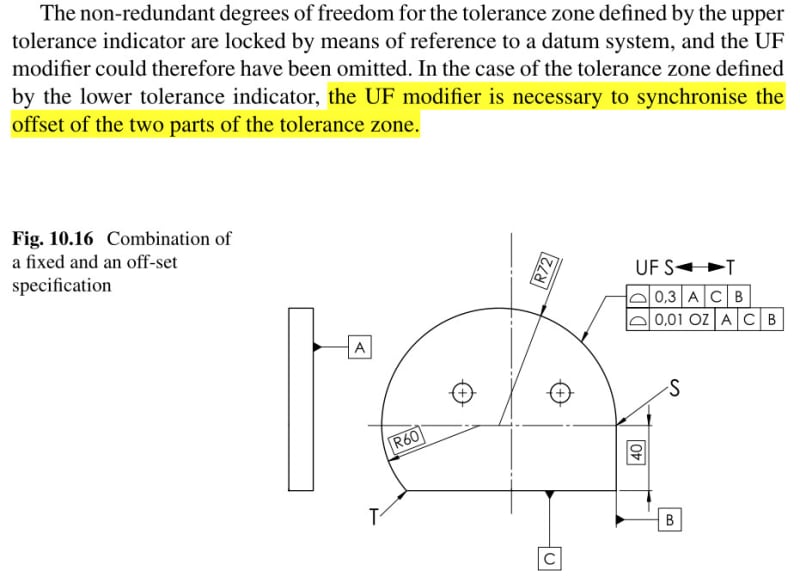
I looked into ISO 1660:2017 and found a figure very similar to the second picture posted by Season. In that figure (B.8), the UF modifier is specified before the between notation, but the note given right below the figure says that: "Because all the non-redundant degrees of freedom for the tolerance zone in Figure B.8 are locked by reference to a datum system, the UF modifier could have been omitted without changing the practical meaning of the specification."

I personally think that this statement is inconsistent with the logic of the independency principle existing in ISO GPS, therefore would agree with the text highlighted by Season and apply the UF modifier in both cases (assuming the intent was to synchronize the expansion of all tolerance zones in question).

EDIT: An alternative to the UF, would be to spwecify the CZ modifier in the tolerance indicator.
 
pmarc said:
If the first case posted is meant to show a single irregular surface, then I am not sure I see a reason for the use of the between notation.

I looked into ISO 1660:2017 and found a figure very similar to the second picture posted by Season. In that figure (B.8), the UF modifier is specified before the between notation, but the note given right below the figure says that: "Because all the non-redundant degrees of freedom for the tolerance zone in Figure B.8 are locked by reference to a datum system, the UF modifier could have been omitted without changing the practical meaning of the specification."

I personally think that this statement is inconsistent with the logic of the independency principle existing in ISO GPS, therefore would agree with the text highlighted by Season and apply the UF modifier in both cases (assuming the intent was to synchronize the expansion of all tolerance zones in question).

EDIT: An alternative to the UF, would be to spwecify the CZ modifier in the tolerance indicator.

Ok. Understood.
So what I learn from this discussion is that to be "safe" / conservative just add UF. No harm no fault.
But one of my follow up question is: do we ever want to have those Tolerance zones un-synchronized? ("assuming the intent was to synchronize the expansion of all tolerance zones in question")

 
greenimi,

I don't know if there would ever be a need to unsynchronize the expansion of the tolerance zones. But even if not, the default rules of ISO GPS language are what they are. So one better explicitly does something on the drawing to impose the synchronization.
 
pmarc

Thanks for your valuable comments, you always give us a guide and light on both ASME GD&T and ISO GPS system.

Season
 
Season said:
Thanks for your valuable comments, you always give us a guide and light on both ASME GD&T and ISO GPS system.

Season,

I agree with you in using the word always in your statement above.


SeasonLee, greenimi,

Thank you both for the kind words.
 
pmarc said:
I looked into ISO 1660:2017 and found a figure very similar to the second picture posted by Season. In that figure (B.8), the UF modifier is specified before the between notation, but the note given right below the figure says that: "Because all the non-redundant degrees of freedom for the tolerance zone in Figure B.8 are locked by reference to a datum system, the UF modifier could have been omitted without changing the practical meaning of the specification."

I personally think that this statement is inconsistent with the logic of the independency principle existing in ISO GPS, therefore would agree with the text highlighted by Season and apply the UF modifier in both cases (assuming the intent was to synchronize the expansion of all tolerance zones in question).

EDIT: An alternative to the UF, would be to spwecify the CZ modifier in the tolerance indicator.
pmarc,

Reading a little more your replay I would say that the statement from ISO1660:2017 might not be consistent with the logic of Independency principle but for sure it is consisent with other ISO standards and concepts (ISO5458:2018 for example). What I meant to say is that even for position callout (groping features of size) if all non-redundant degrees of freedom are locked, the CZ modifier is not needed and could have been omitted. So, at least they are consistent (from one ISO standard to another) in something.....


greenimi,
Despite that the OZ profile is relative to three datums, the OZ modifier introduces additional transformation of the profile tolerance zones and a possibility that the transformation may be applied independently to each feature between the indicated points. Therefore, I am not sure I would say that the statement from 1660 is consistent with what 5458 says.
 
Status
Not open for further replies.

Part and Inventory Search

Sponsor