Continue to Site

Eng-Tips is the largest engineering community on the Internet

Intelligent Work Forums for Engineering Professionals

  • Congratulations IDS on being selected by the Eng-Tips community for having the most helpful posts in the forums last week. Way to Go!

Perpendicularity callout with curved datum

bc23

Mechanical
Mar 7, 2025
17
I re-created this drawing for illustration purposes. All the flat sides/surfaces are actually not flat (so cannot be used as datums).
The intention is for dia4 hole to be perpendicular to curved surface (R10). But is this FCF correct? (whether by ASME or ISO)
If Datum A was re-defined as a specific line on this curved surface, would it be legal? (But it would be difficult to measure also)
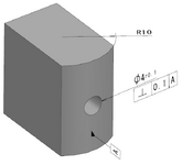
1744001411806.png
 
Replies continue below

Recommended for you

How odd.

3.46 PERPENDICULARITY
perpendicularity: the condition of a line element, surface, tangent plane, feature’s center plane, or feature’s axis at an implied or specified basic 90° perpendicular) angle relative to one or more datum planes or datum axes.

So, no to specific line.

However, if there is perpendicularity to an axis then a plane can be constructed through the axis and where that plane intersects the outer surface, one can create a tangent plane. However, that feature might be anywhere on that plane and need not intersect the axis. If that is acceptable, that feature control frame will do it.

A position geometric characteristic tolerance would act similarly, but restrict the true position to passing through the axis.
 
bc23,

Is this your drawing, or are you trying to interpret something somebody else has done?

Your hole can be perpendicular to your datum in one axis only. Your curved face defines an axis, at least, geometrically. Have fun figuring out where this axis is in your inspection lab.

If you are fixturing to weird shapes, look into datum targets.
 
It sounds like the OP wants the axis of the hole to be perp to a theoretical plane that is tangent to the arc.
 
I re-created this drawing for illustration purposes. All the flat sides/surfaces are actually not flat (so cannot be used as datums).
The intention is for dia4 hole to be perpendicular to curved surface (R10). But is this FCF correct? (whether by ASME or ISO)
If Datum A was re-defined as a specific line on this curved surface, would it be legal? (But it would be difficult to measure also)
View attachment 7894
"IF" datum A was a datum target line, with a specified location it would work. Or, if an additional datum (B?) was specified in the FCF which would orient Datum A - that would work.

As is - the orientation relative to Datum A is unspecified.
 
I would say that a datum target line alone cannot sufficiently constrain orientation to make a perpendicularity control useful.
Or maybe perpendicularity works, but adding the tangent plane modifier could be something to consider...or maybe not...
 
Or maybe perpendicularity works, but adding the tangent plane modifier could be something to consider...or maybe not...
A single straight line as the only auxiliary element for datum establishment cannot fully orient a plane.
 
A single straight line as the only auxiliary element for datum establishment cannot fully orient a plane.
I am thinkg the other way around. make the hole a datum feature and then orient the curved surface to the hole with the perpendicualrity and T modifier.
I am looking to establish a relationship between the curved surface and the hole hence a slight adjustement to get this relationship is what I am thinking could be a good idea.
 
I mean this could work using a cmm to establishing datum with a CMM.

Think about how this has to be restrained in CNC in a fixture. Even thou the opposite face is not flat , the surface would have to be held consistent for tooling. The fixture would simulate a sine plate . To make datum A to held equal to centerline . Then the hole can be held perpendicular , that would be upto the shop.

This Done often with shafts with holes held to centerline.

Far as inspection I would throw this up on a magnetic sine plate. On a surface plate or pick multiple hits with cmm probe. To establish center line . Then continue to inspect hole perpendicular. .
But is thus allowed with ASME rules?
This may be a good application of profile of surface?
Either way no problem mfg or inspecting.
 
Yeah defining perpendicularity to a curved surface like that is tricky. If you really want the hole axis normal to the R10 surface, you’d need to define datum A as a tangent plane at the point of intersection but that's a pain to inspect.
Might be cleaner to just define perpendicularity to the center axis of the part if that makes sense functionally. You fixturing off the curve?
 
Define the plane tangent to the arc at its quadrant as datum target plane A1.

Next, define datum targets B and C on some other features of the part to fully and repeatably immobilize the part for the check of the perpedicularity tolerance.

Then, specify the following, or similar, note (taken from para. 7.24.10 in Y14.5-2018 or para. 4.24.14 in Y14.5-2009):
WHERE ONLY DATUM FEATURE A IS REFERENCED, DATUM FEATURES B AND C ARE INVOKED ONLY TO RELATE THE TARGETS THAT ESTABLISH DATUM A.

Finally, add the missing diameter symbol in front of the perpendicularity tolerance value and keep A as the only datum reference in that callout.
yeppers opposite face and and adjacent face
 
It's only missing a diameter symbol if there is a fixed plane to be perpendicular to. If the requirement is only to be perpendicular to the axis then there is no need for a diameter symbol.

Yet again a case of wanting a solution to a problem that is not completely stated.

The position geometric characteristic control forces the true position of the hole to be at the point of tangency if there is no offset basic dimension. In that case the diameter symbol would be appropriate.
 

Part and Inventory Search

Sponsor