Hi,
I have a bores that has two features that serve as stops for the items that are press fit.
There is a perpendicularity call out to datums A-B
Is this simply stating that both of these features must be perpendicular to 0.15 to both datums A and B?
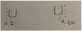
Also will the tolerance zone for both sides be 0.15 as seen in image 2 ?
Image 1
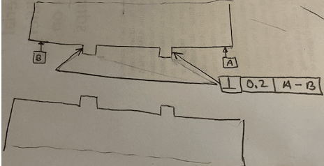
Image 2
I have a bores that has two features that serve as stops for the items that are press fit.
There is a perpendicularity call out to datums A-B
Is this simply stating that both of these features must be perpendicular to 0.15 to both datums A and B?
Also will the tolerance zone for both sides be 0.15 as seen in image 2 ?
Image 1
Image 2