Continue to Site

Eng-Tips is the largest engineering community on the Internet

Intelligent Work Forums for Engineering Professionals

  • Congratulations KootK on being selected by the Eng-Tips community for having the most helpful posts in the forums last week. Way to Go!

Perpendicularty to common datums

Status
Not open for further replies.

umatrix

Mechanical
Jul 18, 2013
62
Hi,

I have a bores that has two features that serve as stops for the items that are press fit.
There is a perpendicularity call out to datums A-B

Is this simply stating that both of these features must be perpendicular to 0.15 to both datums A and B?

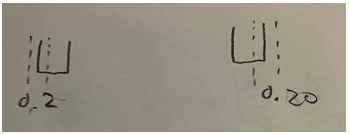
Also will the tolerance zone for both sides be 0.15 as seen in image 2 ?

Image 1
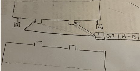
Screen_Shot_2023-11-17_at_11.46.20_AM_pkp0ho.png

Image 2
Screen_Shot_2023-11-17_at_11.46.04_AM_qafyos.png
 
Replies continue below

Recommended for you

Since it is 0.2, not 0.15 that's a problem. Also pointing to a corner is ambiguous but certainly doesn't indicate both outer faces.
 
3DDave , thanks. I corrected the sketch. I also took a look through the ASME Y14 standard but did not see anything on using ,multiple cylindrical datum features for perpendicularity , like what is done with run out.
 
That's a big failing in the standard. They spend so much effort on so many clever diagrams they obscure the expectations. Nothing wrong with this use as an axis is defined. They like total runout for their example because it's old habit.

The effect of the controls overlap for this case. You could also use profile of surface if you added SEP REQT to the feature control frame.
 
I also took a look through the ASME Y14 standard but did not see anything on using ,multiple cylindrical datum features for perpendicularity
A couple of things... First, the standard can't show every possibility, but why would it be problematic to have perpendicularity reference a common datum (hypenated)?
Second, are those two features (stops) cylindrical or square/planar? I ask because if the perpendicularity is applied to 2 features of size, that wouldn't be allowed because perpendicularity can't control the location between them. Your sketch seems to be pointing to the surfaces. Just wondering about the intent.

John-Paul Belanger
Certified Sr. GD&T Professional
Geometric Learning Systems
 
Hi, umatrix:

According to your revised images, "both of these features" refer to two surfaces (flat with ring shapes). They don't refer to the stopper (feature of size) as you imagined.

Datum feature "A - B" is not the same as both datums A and B. "A - B" refers to axis of the combined bores.

Your FCF (feature control frame) is valid. Also, you should add a center line to your first image.

Best regards,

Alex
 
Belanger, the main problem is my knowledge of GD&T
I have several books on the topic, Al and Scott Neumann gd&t book and course and Alex K’s book.

I find it terribly difficult to learn GD&T from a book/ video, and find it slow going.
My next approach is going to be a course and a community college. I see that you teach GD&T, and tolerance stack up, specifically stacks with run out and concentricity. That is exactly what I’m trying to do but without a solid foundation. Do you have any recommendations for any books or other materials that deal with tolerance stack ups of runouts ?
 
The stack method I often use (and teach) is similar to the method used by Alex Krulikowski, so if you want a self-study book on stacks, you can look for his materials. For stack purposes, position, runout, and concentricity are all treated the same. The biggest advice I can give about stacks is to get proficient in determining the "stack path" -- that's a chain of dimensions that all connect from a starting line to a finish line; the path will often include traditional dims/tols (plus/minus) along with geometric dims/tols.

For your picture, I envision datum A-B as a common datum plane, not a common axis. But if the footprints of those two stops are just a small area, then you don't need B, because A is already a continuous surface. But feel free to describe the part in more detail or ask further questions.
 
Ditto what Garland23 said. Just realize that for stacks, there is no standard method (unlike GD&T, which has a standard for its symbols and rules). But I think that Krulikowski's is the most popular method used in industry, and it's the method that I also teach for stack-ups.
FYI, his books are now sold through SAE, not from his own company.
And that's a good point about datum A-B that I hadn't thought of: if they are not truly interrupted then no hyphenation is needed.

John-Paul Belanger
Certified Sr. GD&T Professional
Geometric Learning Systems
 
Hi Garland23 and Belanger. I like Alex Krulikowski's GD&T book. I will order the tolerance stack book. Thank you for the suggestions.
 
While we're on the topic of stacks now... Belanger, what other stack methods are there? Other than the scrap-paper winging-it method, I only know about Krulikowski's.
 
The best way to start is to avoid designs that have stacks. After that, spend time doing tolerance allocation based on functional requirements. Finally, use variation modeling based on factory supplied measurements of actual produced variation to predict process conformance, noting that the paper-only analysis of rigid limits can lead to expensive production and still have unusable parts produced.

The tolerance allocation should be based on functional limits, such as part/feature strength, in addition to the simple geometry fit.
 
Garland23 -- The various methods are mostly the same in essence (find the path/loop) but they differ in how the spreadsheet is laid out. The other main method is a format that tallies up the nominal values and the ± tolerances, all in separate columns. The main authors who use that method are Meadows and Fischer.

John-Paul Belanger
Certified Sr. GD&T Professional
Geometric Learning Systems
 
umatrix,

You may have two pins that are fitted on both sides of the bore, i.e. one pin at datum A side, and the other at datum B side.
They are press fitted and the protruded feature on each side stops the pin on corresponding side.
Considering these interaction of the bore, the stopper, and the pin, you may NOT need common datum feature A-B. I guess you'd better control the perpendiculariy of both stoppers seperatly. That is, perpendicularity of the stopper on the LH side of your figure to datum feature A, and perpendicularity for the stopper on the RH side to datum feature B.
 
Status
Not open for further replies.

Part and Inventory Search

Sponsor