Continue to Site

Eng-Tips is the largest engineering community on the Internet

Intelligent Work Forums for Engineering Professionals

  • Congratulations waross on being selected by the Eng-Tips community for having the most helpful posts in the forums last week. Way to Go!

Pinned vs Fixed Connections in Practise 3

Status
Not open for further replies.

structuree

Structural
Feb 20, 2022
10
I'm trying to get my head around how pinned vs fixed connections appear in practise. I'm struggling to identify whether a connection will result in an induced moment. It doesn't always seem as straightforward in practise as it does in theory.

For example, I am aware that typically a connection with 2 x bolts would be designed as pinned, and you wouldn't consider it as taking any moment, but you add 4 or 6 bolts, and you're probably trying to crank moment into the connection. Where is the line drawn?
 
Replies continue below

Recommended for you

If you strengthen a plate - say, an angle cleat or end-plate - too much, it will not deform plastically (along some yield lines the designer can expect) due to bending or bearing against the bolt before the bolts fail in direct tension or shear. Bolt failure (shear, tension) is almost always a brittle failure mode. This is a concept of ductile design found in e.g., Eurocodes and probably also in the American standards. Thus, I do not see much use in such a lemma - we design buildings for ductile ultimate failure, stability and stiffness, i.e. serviceability.
 
This is a question that I had during school and eventually just pushed down like many others once realizing what "getting into it" required, but since we're talking about it...
This connection MIStructE_IRE showed, we'll say the bolts are only designed for shear, evenly distributed to each bolt from vertical loads.
But when you load the beam, it will want to rotate at the ends. That rotation will be resisted by the uppermost and lowermost bolts, increasing the amount of shear load, and that wasn't accounted for in design.
My understanding in this situation is that due to the bolt hole tolerances and lack of restraint at the flanges, the beam will not actually put any significant amount of "rotational" shear force into the bolts.
But that's where I stopped, taking that statement at face value, shrugging and moving on. But looking at this connection with 8 bolts in a line, it's hard to assume the top and bottom bolts won't see any additional shear from beam rotation under design loads.

Not to mention that beam rotation will also put a tension force at the top of the weld between the plate and support beam.

1_ttpwua.png
 
Lets say the beam was infinitely rigid, then no matter how many bolts you have there, they all remain in shear. No tension and no rotation.

Now obviously that’s not the case for any beam, but designing it as pin-pin gives you, to my mind, enough midspan stiffness to avoid mobilising any significant moment at the ends.

In reality however, nothing other than a pin is truly pinned. Every connection has a certain percentage fixity.

Check this one out - the temporary stability of a 4 bolt “pin” before the masonry wall under was built.. So it has some degree of fixity but we still call it pinned.

414343BC-16EE-4973-B814-0B00FF8CAF34_hveflv.jpg
 
That's a good point. The beam designed as pinned is more stiff than if it were designed as fixed, and the stiffer it is the less it rotates at the ends and potentially overloading the bolts.
 
Dik is correct about the lemma. I do not have a source now to quote but a think that it can be derived easily from the Lower bound theorem of plasticity that states:

" If an equilibrium distribution of stress can be found which balances the applied load and nowhere violates the yield criterion, the body (or bodies) will not fail, or will be just at the point of failure"

Take a frame with a ideal pinned connection and obtain the bending moment diagram at collapse, now substitute the pinned connection by a rigid connection. The previous bending moment diagram "balances the aplied load and nowhere violates the yield criterion", so the load is a lower bound, which means that the system has been strengthened or at least the collapse load has not changed.

Of course that this only applies for ductile failures. Tomorrow i'll research a little bit to improve my comment.
 
Italo01 said:
Of course that this only applies for ductile failures.
Which makes sense. But stated in isolation it is a dangerous theorem to go throwing around.

Many if not most of failures that we are concerned about aren't covered. AKA buckling failures and brittle failures. Furthermore serviceability and repeated actions are not covered as it implicitly tolerates plastic deformation. So as far as I am concerned it not a suitable theorem in the real work.

Take my picture example or BAretired's example. In my example I'd conjecture you'd likely get local plastic yielding at normal serviceability wind loads. Repeated and alternating loads could very much lead to failure. In BARetired's example you could readily get a buckled column and complete collapse.
 
dik said:
barring instability issues, if you strengthen any part of an structure, the resulting structural system will not be diminished in strength. It might not be improved, but it will not be weakened...

I've got to second human909 on this with a recent hand-wringing experience:

Say I have a working [software] structural model - all green all good. Then some well intentioned coworker comes along and "strengthens" all of my beams and columns and braces for me overnight.
[ul]
[li]Is the building "weakened" at any point? I guess not.[/li]
[li]Is the building "improved"? Depends on the fabricator I suppose.
(E.g., "connections will be cheaper if we just make all of these beams/braces/columns the same size instead of 'optimizing' each one").[/li]
[li]Will the structural system still pass all of the code checks that the previously "working" (SMF/BRBF for example) structural model passed? Most likely not.
(E.g., my BRB A_sc (brace area of steel core) got increased by 4in^2 - now I need 12 anchor bolts instead of 8, and my footing needs to be 12" thicker to meet code, but the building isn't "weaker" than it was before.)[/li]
[/ul]

So dik's lemma may still hold true in a general sense of the structure not being "weaker", but it can certainly have unintended consequences, which BA/human909/Italo/and others were getting at. Specifically when it comes to (but not limited to) seismic design, which is what human909 is pointing out I think. Note that I'm differentiating between plastic/ductile design and seismic specific capacity based design. Seismically "special" structures are frustratingly sensitive to what might seem like a minor change in the grand scheme. But this is way off the pinned vs. fixed OP...sorry, OP.
 
Human909 said:
Which makes sense. But stated in isolation it is a dangerous theorem to go throwing around.

Yes, i agree. One must be very aeare of its limitations.
 
I'm not sure that invalidates the concept because your model would have considered the connection to be fixed in the first place and your reactions determined would reflect this.

Major Edit: I was thinking about this last night and my paraphrased recall of the lemma was based on reading it 50 years back. I think it's substantially true and I may only have 'brought forward' what I thought was important about it. BART's posting shows a 'big hole' in it. I tried to locate it a decade back and couldn't; perhaps it's been 'withdrawn' or whatever they do with lemmas. I should have added that Feldberg is out of my vocabulary, now.

Rather than think climate change and the corona virus as science, think of it as the wrath of God. Feel any better?

-Dik
 
dik said:
I'm not sure that invalidates the concept because your model would have considered the connection to be fixed in the first place and your reactions determined would reflect this.
This has to be explained more as it seems to miss the point. I'm unsure who you are addressing here, but you seem to be trying to have it both ways by claiming the model would have considered a fixed connection scenario. This is contrary to the entire point, models often treat end conditions as pinned when they are in fact not.

The point being that there ARE circumstances where a should a pinned connection be semi-rigid or rigid it can readily increase the loads at a point away from the connection. In the wrong circumstances this could readily cause damage or collapse. There is a VERY good reason why some connections are allowed to translate or rotate.
 
I put BAretired's case into a Mastan2 2nd order inelastic analysis, since I'm learning the software. I used a 100UC14.8 column and 530UB82 beam (Australian sections), with a pin joint between column and beam. I set the applied load to give the code capacity axial force in the column for the pin support case. Analysis was in the plane of the frame only.

For the case of pin at A, the load ratio at failure was 1.11 (the inverse of the code capacity reduction factor of 0.9 - impressive! or coincidence).

For the case of fixed support at A, the load ratio was 0.98. So the reduction in capacity wasn't in proportion to the increased load in this case and the capacity factor seems to have papered over the error in support assumption (in this particular case) - phew!
 
Thanks everyone, this thread has been very insightful so far. More than anything it’s highlighted for me that the designer ultimately has control with regards to how the structure is to behave. But it also seems as though there are some ‘best practise’ design methods that become apparent to a designer with experience - human909 highlighted this well by explaining the consequence of designing a fixed column to footing connection (consequent rotation and cracking of the footing).

Are there any other ‘best practise’ design consideration or widely held practises that I should be aware of that haves consequences in practise?

I also have another question pertaining to a dowel joint - typically modelled as a pin. Take for example a dowel joint connecting a beam to a column, or a slab sitting on top of a capping beam also connected by a dowel. What happens when we grout this up? Or if the dowel was to be fully cast in? With the elements bearing directly on each other, could or should you justify some level of fixity?
 
@Human99: see my revised comment; you are correct in your comments. It's never been an issue, because the connection would have been pinned or rigid and the system designed on that. But thanks to BART for bringing this forward.

Rather than think climate change and the corona virus as science, think of it as the wrath of God. Feel any better?

-Dik
 
dik said:
It's never been an issue, because the connection would have been pinned or rigid and the system designed on that. But thanks to BART for bringing this forward.

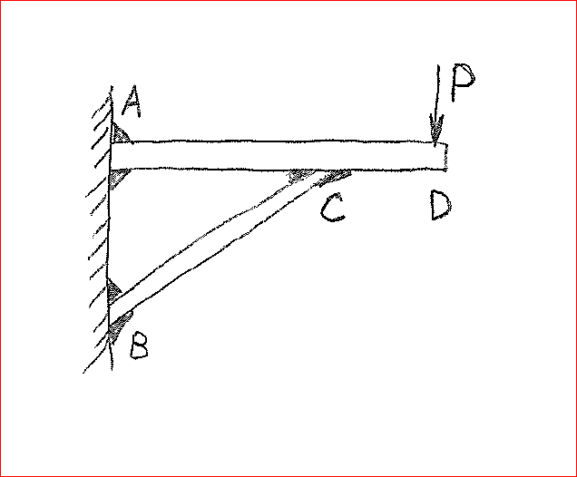
You're welcome dik. A similar situation arose in thread507-491227, quite recently. The OP's sketch is repeated below. I was among those who recommended using the determinate case of having all joints pinned. It turned out that, when all joints were rigid, the horizontal reaction at B, and hence, the axial force in diagonal BC was greater than the case where all joints were pinned. The thread terminated without that point being discussed.

Capture_a3owgb.png


In the propped cantilever example which I mentioned earlier in this thread, fixing the joint at Point A effectively shortens the back span from 3m to 2m, which increases the column load from 2.33P to 3.0P, a ratio of 1.286. The ratio would be still larger if the cantilever length were increased.


BA
 
I've been doing something wrong for 50 years... it's not affected any of my designs and was always applicable, but overall not correct... it seemed like a self truth. I actually feel good about learning this.

Rather than think climate change and the corona virus as science, think of it as the wrath of God. Feel any better?

-Dik
 
Dik, you can take some solace in knowing that, in real life, fixed ends do not exist.

BA
 
You mean there's no inifinitely rigid? [ponder]

Rather than think climate change and the corona virus as science, think of it as the wrath of God. Feel any better?

-Dik
 
Be wary of counting on fixity during erection like shown by MIstruct - almost certainly going to work for an end plate connection like in the picture, but if done with clip angles the beam will just fall to the ground (IME when a contractor didn't properly rig a beam and a drift pin fell out).
 
BAretired,
Are you aware of any beam formula references concerning propped cantilever beams (basically the same diagram your provided with a roller at B)?

For various loading, I've had to model these or use the force compatibility method to get these reactions. Looking for a table or quicker resource.
 
StrEng007,

If support B is a roller, all horizontal forces must go to support A. I guess I don't understand the problem. Could you illustrate an example where the loading requires force compatibility methods to solve for reactions?


BA
 
Status
Not open for further replies.

Part and Inventory Search

Sponsor