Continue to Site

Eng-Tips is the largest engineering community on the Internet

Intelligent Work Forums for Engineering Professionals

  • Congratulations SSS148 on being selected by the Eng-Tips community for having the most helpful posts in the forums last week. Way to Go!

Plane surface datum feature MMB located basically from a higher precedence datum

Status
Not open for further replies.

Burunduk

Mechanical
May 2, 2019
2,513
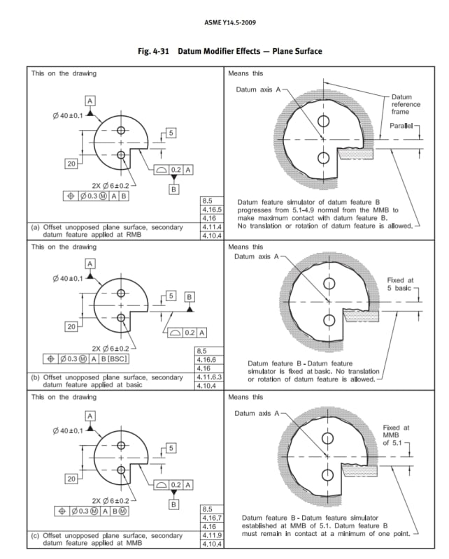
Fig. 4-31, ASME Y14.5, illustration (c):

"Datum feature B must remain in contact at a minimum one point."

With this condition, It looks like if the profile tolerance applied on datum feature B was more than the shown 0.2 and large enough, or the position tolerance for the holes was less than 0.3(M) and tight enough, a pair of holes positioned accurately and passing inspection per the (a) and (b) cases, may be forced out of tolerance by rotating the part all the way to meet the requirement of minimum one point of contact with the datum feature simulator of B at MMB. Perhaps this can be prevented by having the datum feature B toleranced considerably more accurately than the holes controlled with reference to it, but it still seems weird; It looks like MMB and the minimum contact requirement in this case actually make it more difficult to meet the tolerance - unlike for example the case of 4-30 (b) where the scheme makes sense because there is actual datum shift. MMB in fig. 4-31 seems to impose a restriction rather than allowing shift. Where am I wrong?

Screenshot_20200529-155820_Drive_rudh0f.jpg
 
Replies continue below

Recommended for you

Burunduk,

You must be referring to the the 2009 standard. Do you have access to 2018? In 2018 they have adjusted that situation so minimum one point contact is no longer required, rather "one or more maximum material extremities shall lie between the MMB and the LMB."

To your point, the required contact could actually pose a restriction rather than an allowance, and 2018 has adjusted accordingly in Fig. 7-36 and Para. 7.16.7.

 
Jacob,

Indeed I was referring to the 2009 standard. Thank you for providing the update from the 2018 version. It makes more sense to me than the 2009 version of this case. I can see how the requirement in fig. 7-36 which you posted can provide datum shift and allowance for the 2 holes pattern position.
 
It looks like MMB and the minimum contact requirement in this case actually make it more difficult to meet the tolerance

I agree, it could make it more difficult especially if there is significant variation in datum feature B. But that is the way its written.

Jacob is correct, this has been modified in the 2018 standard to provide the behavior we expect from MMB. (note Jacob - you can put the photo in the body of your post with the "image" button on the toolbar with the little icon of a camera).

I think the 2009 definition was written more with physical gauging in mind, especially since the concept of MMB is often utilized with the intent to create a more cost-effective physical hard/fixed gauge - the 2018 the definition lacking requirement for contact provides us with more of the expected behavior of shift, but policing that in a physical gauge is more difficult (perhaps impossible - or impractical in most cases) for a feature which is not "captured" in rotation.
 
Chez,

Just to add on to your comment about gaging. 3DDave (from this forum) had a pretty solid idea recently on gaging a very similar situation and I think it could be adapted quite easily to fit this case.

If you simulate datum feature A with a contractible true geometric counterpart and you put a hard stop at the MMB of datum feature B, you could have some sort of limited top, or covering, to your gage with a small window of width MMB - LMB (assuming your tolerances aren't too tight, I guess). Now you can have gage elements that'll verify the position of the bolt pattern and use another counterpart gaging element to insert into the window/slot - if contact is made with the part, then datum feature B must have an extremity in the MMB - LMB region.

Thanks for the tip on image insertion.
 
The real problem with the 2018 version is that the assembler will require specific instructions in how to establish that gap on the factory floor. Sure, it's easy if they have a CMM at hand to confirm the part placement and my guess is this is a definition that was added by representatives of CMM makers or CMM programmers.

Any idea how, when the mating part has some variation, that this part could be correctly oriented per the '2018 version?

Not that the '2009 (c) case made any sense either, for the same reason.
 
Jacob,

Thats an interesting concept - the idea could be even more simplified (especially for tight tolerances applied to large features - which would require a very thin and very wide gauging element) with a standard feeler gauge of thickness MMB-LMB and just ensure at some point along the feature surface it is rejected/does not fit. Going to have to remember that one, thanks - my other idea, which is maybe more simple than I initially thought and not so "improbable" as I first commented, was to have the datum feature simulator for B movable and spring loaded with a dial indicator set at 0 for LMB (also with a stop for travel on the simulator at LMB - perhaps actually slightly less than LMB so that you could see it move through the LMB limit, I'll leave that to the gauging experts hah) and a hard stop at MMB. As long as your indicator read greater than 0 some element of the surface would be between LMB and MMB.
 
Any idea how, when the mating part has some variation, that this part could be correctly oriented per the '2018 version?

You mean if the part shown was used in a hypothetical assembly? I guess it could be done in the more simplified manner I presented with a feeler gauge.
 
chez311,

I completely agree that a feeler gauge of thickness MMB-LMB would work, to meet the questionable requirements of Y14.5-2018. The feeler gauge should be a spherical ball if that is physically possible (if the tolerances are large enough to enable a spherical ball of the correct diameter to be usable and possibly attached the smaller diameter cylindrical pin to act as a handle).

The reason I call the requirements of the 2018 standard questionable is because I can't come up with a functional case for which the requirement makes sense. The only two conditions that make functional sense to me for this type of datum feature, which I would call a "locatable, but non-overlapping lower precedence datum feature", are RMB or BSC. With the requirement as written in 2018 the outcome of applying either MMB or LMB to this type of feature seems to be identical. I think a better solution would have been to develop a good definition for this type of datum feature, then limit the allowable datum feature modifiers for it only to RMB or BSC.

Edit: Please forgive the non-word "locatable". Just trying to get a point across without a wordy explanation.

Dean
 
The feeler gauge cannot work at assembly because the user of that gauge does not know what the actual part variation in either of the two parts is in order to duplicate the orientation of the part established at inspection. Does the assembler use an LMC gauge or an MMC gauge or one in the middle without re-inspecting the part the assembler just took off the shelf?

The guarantee of inspection should be that the part has an acceptable assembly solution; if that solution is required to be one that cannot be duplicated at assembly then the criteria for that inspection are flawed. In this case, if the part has to be clocked "just so" in order for the holes to be correctly located, and there is no means to ensure that same "just so" condition occurs at the assembly level then it's a bad concept.

This is not the same as a hole pattern that is such that only one orientation/location solution exists; this will easily be duplicated at the next assembly by merely installing fasteners/pins. This is requiring the surface to hover somewhere in direct relation to a material condition that the installer cannot confirm.

 
3DDave,

I can see the reason for your hesitation. If I were to imagine the mating part for the one in this thread, I would assume that the feature “contacting” datum feature B may not even need to make contact. I am seeing this as more of an assurance of clearance, similar to LMC preserving wall thickness. The “just so” clocking may be fine. I would imagine the intention was to ensure datum feature B does not interfere with the mating surface, and floating somewhere between MMB (mating surface) and LMB would guarantee that.
 
However, that float is saying where the acceptable location for the holes is. Example: If those holes are to locate a laser beam fixture - and the part just barely meets that requirement at part inspection - how will the assembler know how to clock the part to correctly locate the laser beam? If that alignment does not depend on the profile of that and the mating feature why is the profile feature volumetric variation used as a reference? If it is to make contact then it will be RFS.
 
This all illustrates the problem of having opened up the MMB concept to a surface type of datum. MMB is meant to allow for datum shift, which makes sense for a FOS datum because there is containment around the feature, and the shift has touchable boundaries. But for the given example in the OP, the shift doesn't have touchable boundaries in the usual sense.
I know my comment isn't adding much to the discussion; I'm just summarizing my overarching view.

John-Paul Belanger
Certified Sr. GD&T Professional
Geometric Learning Systems
 
This does not illustrate a general problem with extending MMB to planar surfaces, or other non-size datum features. The issue is only with this particular situation, where the datum feature in question does not overlap the origin of the DRF established from higher precedence datum features (no vector that is normal to the surface of the datum feature passes through the origin of the DRF established using the higher precedence datum feature(s)).

If the datum feature is a surface that overlaps the origin of the DRF established using higher precedence datum features, then MMB or LMB work fine.

As I said above, for the type of datum feature in the figure that Burunduk posted, I think the application of MMB or LMB should not be allowed. Only RMB and BSC make sense.

As much as I think MMB or LMB should not be allowed for this type of datum feature, the requirements in Y14.5-2018 are a reality, so there is still this question about whether a feeler gauge could be used to as part of the verification. If the part is placed on a functional gage, part of the requirement is to ensure that "one or more maximum material extremities" on the datum feature is between the MMB and LMB. All that would take is using a feeler gage between a physical MMB surface and the datum feature. Now that I re-read the requirements, I think Chez311 is completely correct about a conventional feeler gauge being adequate. As long as the feeler gage with thickness = MMB-LMB can be made a no-go as the part is moved towards the MMB surface, then it meets the requirement.

Dean
 
A feeler gauge is great for inspection - it does nothing for assembly. If one only cares about passing inspection then opening up the tolerance values will accomplish that. Omitting the requirements will do even better. However, if the intention is to ensure the accepted part will be installed correctly, the feeler gauge cannot work.
 
I don't think this sort of requirement, with MMB or LMB specified with this type of datum feature, could ever be an assembly requirement. Maybe I'm missing something. Can anyone describe a functional case for which the requirements in Y14.5-2018 for MMB or LMB applied to this particular type of datum feature would be needed?

RMB or BSC for this type of datum feature will work fine, but not LMB or MMB.

Similar to the fact that BSC cannot be applied for an overlapping lower precedence datum feature (unless a unilateral, fully inside the material profile is specified on the datum feature, I suppose), I think the standard should include a prohibition on MMB or LMB for the non-overlapping datum feature brought up in this thread.

Dean
 
Dean -- it's true that this dilemma is not a blanket condemnation of surfaces being referenced at MMB -- Fig. 7-33 also has a surface datum with MMB but it at least has limits to the shift in both directions. So I amend my comment to complaining about the type of datum being discussed here, where the shift is unbounded in one direction except by a theoretical zone. Thanks for pointing that out.

I'm not quite sure what you mean by "overlapping the origin of the DRF" -- Fig 7-33's datum B is well offset from origin of the DRF (i.e., no overlap).
This is not to disagree with the concept; I'm just trying to find the best words to capture our dilemma, which is that datum shift is not physically limited (though theoretically limited).

Edit: By overlapping, do you mean that the datum feature in question (such as Fig. 7-33) extends above and below the origin, thus constraining both directions of datum-shift rotation?

 
The feeler gauge cannot work at assembly because the user of that gauge does not know what the actual part variation in either of the two parts is in order to duplicate the orientation of the part established at inspection.

That could be a sticking point, unless the mating feature is very accurate I could see where issues might arise. To echo as some others said I'd be dubious of the practical application for such a specification as written in 2018 anyway. The first thing that comes to mind is a maximum air gap requirement, but even this doesn't quite satisfy that requirement since only part of the surface must be between the MMB/LMB boundary - ie: the feeler gauge does not need to be rejected at every point, only at a minimum of one point.

The guarantee of inspection should be that the part has an acceptable assembly solution; if that solution is required to be one that cannot be duplicated at assembly then the criteria for that inspection are flawed. In this case, if the part has to be clocked "just so" in order for the holes to be correctly located, and there is no means to ensure that same "just so" condition occurs at the assembly level then it's a bad concept.

This is not the same as a hole pattern that is such that only one orientation/location solution exists; this will easily be duplicated at the next assembly by merely installing fasteners/pins. This is requiring the surface to hover somewhere in direct relation to a material condition that the installer cannot confirm.

This brings up an interesting point about the nature of MMB. Isn't it possible that even with a pattern of holes specified MMB that features referencing the pattern of holes at MMB could result in an assembly location/orientation which would not pass during inspection? If a part must be shifted all the way to one side in order for a feature to pass, the part could still be shifted all the way to the opposite side during assembly. How does one guarantee this will be duplicated during assembly if this is the case?
 
Hi John-Paul,

Please pardon my use of an unnecessary term (overlapping), but yes,
Belanger said:
By overlapping, do you mean that the datum feature in question (such as Fig. 7-33) extends above and below the origin, thus constraining both directions of datum-shift rotation?
That is exactly what I meant. I should have used the term "Offset" though, so I need to apologize for that bit of confusing terminology I let slip in. Offset is the term applied to this type of datum feature in both 2009 and 2018 versions of the standard. As I think about this more, trying to classify what is an offset datum feature and what is not offset based on the characteristics of the feature, rather than based on how they behave as a datum feature (constraining rotation in only one direction) is too messy and problematic. Just using the term offset, based upon whether it constrains rotation in only one, or instead both, directions should be fine.

Back to the point I think is important to discuss, for these offset lower precedence datum features, I think MMB and LMB should be prohibited, so only RMB or BSC could be applied. I don't think the way the 2018 standard limits the rotation in the non-constrained direction, using the other material boundary, can ever be a function-based limitation, so I think this should be changed in Y14.5. Maybe I'm missing something, but I'll stick to this view of the situation for now.

Dean
 
Status
Not open for further replies.

Part and Inventory Search

Sponsor