Continue to Site

Eng-Tips is the largest engineering community on the Internet

Intelligent Work Forums for Engineering Professionals

  • Congratulations cowski on being selected by the Eng-Tips community for having the most helpful posts in the forums last week. Way to Go!

position tolerance

Status
Not open for further replies.

dho

Mechanical
May 19, 2006
255
FORTUNE 500
(COUPLE DAYS AGO, I POSTED "FORTUNE 500". I WAS NOTIFIED THERE WERE 5 OR MORE FOLLOW UP THREADS, WHEN I TRIED TO OPEN IT, I GOT SYSTEM ERROR RESULTED TO RESET MY PASSWORD.... AND MY POST WAS GONE.)
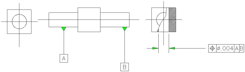
is this position tolerance correctly specified ? if not, the supporting ASME Y14.5 clause?
thanks.
p-ab_tupyr9.jpg
 
Replies continue below

Recommended for you

How does the part function
How do the features function in relation to each other?
 
Once datum A is established, datum B doesn't seem to add any further control (think about "degrees of freedom"). So I would question the usage of the two datums.
Often in this situation the two will be combined into a hyphenated datum: A-B. But as JNieman wrote, function will dictate the correct approach.

John-Paul Belanger
Certified Sr. GD&T Professional
Geometric Learning Systems
 
Hello Dho,
position tolerance is only controlling axis offset from datum but does not control orientation of the hole.
 
Dho:

I agree with Vishal2015 relative to the lack of orientaion control. Assuming you want the hole oriented to the sides of the square, may I suggest using one of the end faces or the longitudinal width (center-plane datum) of the square to control the orientation (rotation) of the hole "around" the datum axis (established by A or A-B as Belanger suggested in an earlier post).
 
this is a make to print job for a fortune 500 company.
i understand their requirement is the hole C.L. intersects the "shaft" center line "right on" and at exact 90 degrees. NOT critical in longitudinal and radial clocking.
i think "position A, B" is wrong. the "minimum" should be "position A-B".
i was looking for A Y14.5 clause saying two axes in the same direction can not be assigned to primary and secondary datum together.
thanks.
 
dho:

Regarding you response "i understand their requirement is the hole C.L. intersects the "shaft" center line "right on" and at exact 90 degrees. NOT critical in longitudinal and radial clocking"
It is my understanding that GDT controls only apply in the view shown. Therefore, since the hole is only shown in the right-end view and not in the front view (between the two end-views); in the front-view the hole could mis-orient (tilted "vertically" left or right) and still appear to pass through and be perpendicular to the datum axis in the right end-view. Given this, I suggest showing the hole in the front-view to preclude any misunderstanding as to the hole's position requirement of 90-degrees in both view - Y14.5 para 1.4(j) and 1.4(i) would then apply.
 
mkcski said:
It is my understanding that GDT controls only apply in the view shown.

This is incorrect. GD&T controls apply with respect to the datum reference frame. I'm pretty sure that notion came from some figures in the 1994 standard that stated that some orientation tolerances only applied in the view shown. Those notes have been removed from the 2009 version and I think the reason might be because people were thinking that it applied across the board to all geometric tolerances. I'm not positive about the reasoning though.


John Acosta, GDTP Senior Level
Manufacturing Engineering Tech
 
powerhound:

Thanks for the clarification. It helps my understanding of the subtleties of GDT. However, paragraph 1.4(j) says "shown at right angles". Then how can one apply the default perpendicularity (90-degrees)if the relationship is not shown?
 
That is regarding the implied 90 rule. This is so whenever 90 degree angles--or features shown at 90 degree angles to each other--are shown, you don't have to call them out at 90 degrees. That's all that fundamental rule does. It doesn't say--or mean--that all geometric tolerances apply only in the view they are shown.

John Acosta, GDTP Senior Level
Manufacturing Engineering Tech
 
powerhound:

I think you misunderstood the intent my response. Let me try again. My only concern is that the "right angle" relationship is not shown (literally) in the front view to have rule 1.4(j) apply. Assuming the tolerance zone is 90-degrees in the front view sounds "dangerous" to me.

Or...are you saying the tolerance zone, even thought it is not "shown", is by default 90-degrees because the (2) left-over motions - movement along the axis and around the axis - would not alter (do not impact) the 90-degree relationship.
 
All I'm saying is that GD&T is not view dependent.

If this drawing was done with correct GD&T, one of the datum features would either be a face or a centerplane of the square feature. Then using a correct position callout would constrain the hole perpendicular to that datum reference, no view would be needed to imply 90 degrees. It would be explicitly stated through the callout. There's no good reason to deliberately leave a constraining datum reference off just so you can use the implied 90 rule.

John Acosta, GDTP Senior Level
Manufacturing Engineering Tech
 
powerhound:

This was exactly my suggestion in 4/12 reply. Sorry it tool so long to get to a common position.

I just discovered the forum a few months ago and look forward to reading and "talking" to the "regulars" like yourself. I have been "around" GDT for over 35 years - teaching, consulting (local to my home in PA). I critique drawings at my place of work - not my primary duty. I have a Senior Level Certification issued in 1999. I periodically search for and buy new texts/materials (Don Day, Alex K, Al N. etc) to improve my GDT "database". Your willingness to advance understanding by responding to questions is commendable and the dialog is much appreciated.
 
Status
Not open for further replies.

Part and Inventory Search

Sponsor