Continue to Site

Eng-Tips is the largest engineering community on the Internet

Intelligent Work Forums for Engineering Professionals

  • Congratulations KootK on being selected by the Eng-Tips community for having the most helpful posts in the forums last week. Way to Go!

problem with patterned tolerance of position 5

Status
Not open for further replies.

LCform

Mechanical
Jan 13, 2016
139
Hi All

Shall I ask you to explain me a bit more about the context of this link ?

here

I need to apply a tolerance of form on a piece with similar shape, that the small holes that are patterned aroun the center should be symmetric repect to the vertical axis of symmetric of the big circle, ( which is the most important)


I tried reading it , but didn't grasp much out of it
 
Replies continue below

Recommended for you

LCform,

Your diagram shows a composite feature control frame. This calls up a fairly accurate pattern of holes, located somewhat sloppily on the part. In the real world, you need fairly accurate tolerances to ensure screws pass through their clearance holes. You do not necessarily care where your part gets located. If your vendor is drilling holes in a casting, he can take advantage of this.

If your pattern must be located accurately to the OD, this does not help you.

--
JHG
 
The example does not control symmetry, it controls position of the pattern. If you need symmetry, use a symmetry tolerance.

The part does not have a vertical axis. You will need some feature that defines a plane of symmetry.
 
This looks like an example from the AMSE standard. From memory ASME does not let use you the symmetry symbol. It uses position instead. Here I think you need position.
You need to be careful as form and position are two different things. Example: The round plate may need a roundness tolerance or cylindricity tolerance especially if you are using the ISO standards and not ASME.. This is form control. (the shape of the item). Positional tolerance controls the position of an item, or hole pattern etc.
The example shown has 2 positional tolerances on the same pattern of holes.
It shows that the pattern of holes needs to be within the dia of 0,5mm to itself but also the holes need to be square to the face you are drilling into within this tolerance. The positional tolerance applies through the thickness of the part. There is also another larger tolerance. This controls the hole pattern relative to the centre of the plate. There is more allowance here. This suggests there is clearance to the OD of this plate to the mating ID of the other part, or for some reason its less important to control the pattern to the centre of the plate than the hole pattern to itself.
If I did a similar example I would datum the face you are drilling into as datum A. Put form contol on it. IE flatness 0,1mm or similar. Remember form control has no datums in the tolerance control frame. Put the centre of the plate as datum B. Control the roundness if the plate is thin or cylindricity if thick. Put squareness tol on the OD to datum A with dia symbol in it. (this controls datum B to A)Position holes to A/B as the example ish.
 
Symmetry has been back for a long time. It was eliminated from only one version before being reinstated in the next. I recall it was out of the 1982 version , but back in 1994 version.
 
3DDave said:
Symmetry has been back for a long time. It was eliminated from only one version before being reinstated in the next. I recall it was out of the 1982 version , but back in 1994 version.

Just to continue the history:
Kept (symmetry) in 2009 and most likely be out in the next revision (along with its friend concentricity)
 
What will replace them? Any white papers explaining the reason?
 
All here probably know the headaches surrounding those two symbols. So it will be no surprised if they are to be dumped. What will replace them? Well, for those very specialized cases where they're really needed, we can use the old fall-back answer: add a note explaining what you want.
That's better than throwing concentricity on a drawing and having 95% of the people downstream mistake its true meaning.

John-Paul Belanger
Certified Sr. GD&T Professional
Geometric Learning Systems
 
What headaches? They are about as straight-forward a geometry check as one can make. There are a lot of other symbols/concepts that deserve dumping before these.

As I suggested - there should be a white paper explaining the reason for removal. If no one can write up a good argument with a mathematical basis then there is likely not a good reason to remove them.

OTOH the adoption of Voelcker's symbols without a write up of explicit benefits to industry was also done. It added significant complexity to the standard without obvious benefit in time-savings over the notes suggested as replacements for the obvious cases of symmetry about a plane (symmetry) or symmetry about an axis (concentricity).

While I understand the academic argument Voelcker made, the argument included no examples of practical mechanisms that would be accurately described using the methods. Not one, much less** a backlog of drawings that had extensive notes that would be replaced by the compact symbolic notation.

**Colloquially speaking, as it is difficult to be much less than 0.
 
What headaches? They are about as straight-forward a geometry check as one can make.
What headaches? Well, let's see what the Y14.5 committee has said about these very symbols in the Y14.5 standard in the past:

"Irregularities in the form of an actual feature to be inspected may make it difficult to establish the location of that feature’s median points...In such instances, finding the median points of the feature may entail a time-consuming analysis of surface variations. Therefore, unless there is a definite need for the control of the feature’s median points, it is recommended that a control be specified in terms of a runout tolerance or a positional tolerance." (1994, p. 146)

Pretty rare for a standard to add such an editorial! That was softened in 2009 to a non-judgemental reminder that these symbols are "substantially different" than position, etc. But it's no secret that concentricity in particular has been a pain for years because people throw it onto a drawing without understanding the intricacies of "median points." At least in my travels I don't see any other symbol misused in such a way (misused yes, but not in such an integral way to its definition).

John-Paul Belanger
Certified Sr. GD&T Professional
Geometric Learning Systems
 
So where will the committee leave those who do have a definite need to control the feature's median points if they eliminate symmetry and concentricity? Are there so many instances that affect committee members of misuse of these symbols that -something- needs to be done? Because I'm up to my eyeballs in drawings that people made with no consideration for datum selection; it would be simpler to return to implied datums and not have to argue any more.
 
I'm not sure what they intended to do to those who really need it. As mentioned before, you can use a good-old note.
Recall that GD&T is a language (designed by committee) and not a hard science, so there are bound to be such decisions that seem strange or unwise. I myself am perfectly happy to escort concentricity and symmetry to the door.

John-Paul Belanger
Certified Sr. GD&T Professional
Geometric Learning Systems
 
@DeanAllen : shall you please refer me to that ASME example as well ?


The general sign of symmetry has confused me, I also needed the middle circle be symmetric with respect to the axes. this case would become harder with a circle is surrounded in a rectangular shape and its axes should be symmetric regarding to the lines of the rectangle

So as you indicate, this one has no more application ? what is exactly the substitution ? what about the second case I indicated above ?

symm_i75b1e.png
 
I can think of two scenarios for an appropriate use of concentricity that I got from this forum on a thread that addressed this very thing; however, I don't know if the scenarios were real, or just thought up to answer the question to the affirmative. I've never seen an appropriate use nor have I heard of an appropriate scenario for the use of symmetry. Of all the times I've seen these specified, I've never had a case where control of the median points was really the goal. I know my small slice of this pie is by no means all encompassing. Is there anyone here who has actually seen a print with concentricity or symmetry called out where it was the appropriate callout? I'm not asking if anyone can think of an appropriate use, I'm asking if anyone has actually seen it used appropriately.

John Acosta, GDTP Senior Level
Manufacturing Engineering Tech
 
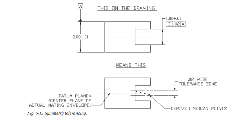
LCform, you wrote that you "also needed the middle circle be symmetric with respect to the axes." But here's the real issue:
How do you find the axis of that circle? That is what sets concentricity and symmetry apart from the position symbol.
Do you really want to find the median point of every opposing element of the circle? Or would the axis derived from the "actual mating envelope" suffice?

John-Paul Belanger
Certified Sr. GD&T Professional
Geometric Learning Systems
 
@Belanger

Thank you very much for your answer, if I have understood your hint, it is important to go top down, meaning from assembly to the parts, to first define the important faces ?
Yes for my case all the centers are important, I did not understand the phrase : "median point of every opposing element"
 
LCform,

I believe I understand the symmetry specification. I don't understand why I would use it. Symmetry should be a refinement of a profile tolerance. Imagine that I apply a 0.1[ ]profile tolerance all around the figure you attached. The symmetry applies a control more accurate than my profile. But why?

Concentricity makes sense if you have a cylindrical datum feature, as opposed to a merely round datum feature. I cannot recall ever doing this, but I do not draw very many shafts.

In either case, you can use positional tolerances.

--
JHG
 
Status
Not open for further replies.

Part and Inventory Search

Sponsor