ATC350X
Mechanical
- Dec 19, 2022
- 9
Greetings Everyone,
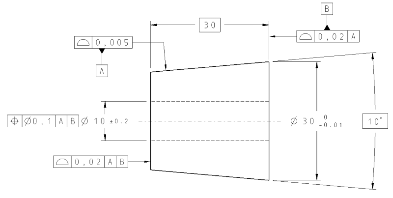
New to the forums and hoping some of you can shed some light on calling out a profile tolerance on a tapered insert. I have attached a picture of a simplified insert that I commonly work with at my company. From what I have been told, the large diameter dimension, length and the angle of the taper are what are important for establishing the part since the insert is placed inside of a tapered bore along with other inserts. The ID is re-finished when all inserts are in place. Therefore, during manufacturing of the insert, it is not crucial to have the ID axis and the cone axis perfectly concentric. To try and show this while holding the taper, the drawings are formatted with the shown GD&T. The way it is supposed to read is "the angle of the taper needs to be held essentially perfect but the entire cone can move radially a little bit about the ID axis". Being newer with GD&T I am not 100% sure what is shown on the drawings is correct and/or makes sense. I have found many examples of profile of a conical surface but nothing quite like this. The only hardcopy standards I have available is ANSI Y14.5M - 1982 (a bit out of date, I know). In this standard I looked at Figures 190 and 191. If I was dimensioning this based on examples, I would simply omit the circular runout tolerance and move the Datum A reference up to the profile tolerance. However, this means the profile in relation to the ID axis will be held extremely tight when it really doesn't have to be. Can anyone provide any input on whether or not the layout of this tolerancing is correct or possibly a better way to do it? I've looked at composite profile and MSS profiling but not sure if that is the way to go. Of course, if further explanation is needed, I can provide that since I am sure I haven't quite explained things clearly.
Thanks in Advance.

