Continue to Site

Eng-Tips is the largest engineering community on the Internet

Intelligent Work Forums for Engineering Professionals

  • Congratulations cowski on being selected by the Eng-Tips community for having the most helpful posts in the forums last week. Way to Go!

Profile of a Tapered Insert 1

Status
Not open for further replies.

ATC350X

Mechanical
Dec 19, 2022
9
Greetings Everyone,

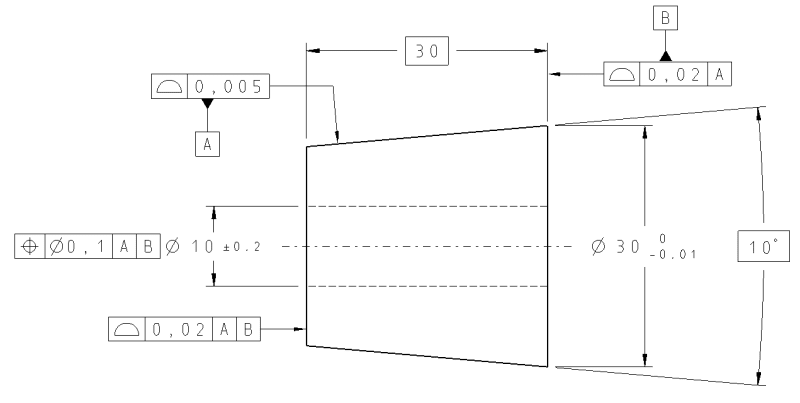
New to the forums and hoping some of you can shed some light on calling out a profile tolerance on a tapered insert. I have attached a picture of a simplified insert that I commonly work with at my company. From what I have been told, the large diameter dimension, length and the angle of the taper are what are important for establishing the part since the insert is placed inside of a tapered bore along with other inserts. The ID is re-finished when all inserts are in place. Therefore, during manufacturing of the insert, it is not crucial to have the ID axis and the cone axis perfectly concentric. To try and show this while holding the taper, the drawings are formatted with the shown GD&T. The way it is supposed to read is "the angle of the taper needs to be held essentially perfect but the entire cone can move radially a little bit about the ID axis". Being newer with GD&T I am not 100% sure what is shown on the drawings is correct and/or makes sense. I have found many examples of profile of a conical surface but nothing quite like this. The only hardcopy standards I have available is ANSI Y14.5M - 1982 (a bit out of date, I know). In this standard I looked at Figures 190 and 191. If I was dimensioning this based on examples, I would simply omit the circular runout tolerance and move the Datum A reference up to the profile tolerance. However, this means the profile in relation to the ID axis will be held extremely tight when it really doesn't have to be. Can anyone provide any input on whether or not the layout of this tolerancing is correct or possibly a better way to do it? I've looked at composite profile and MSS profiling but not sure if that is the way to go. Of course, if further explanation is needed, I can provide that since I am sure I haven't quite explained things clearly.

Thanks in Advance.
 
 https://files.engineering.com/getfile.aspx?folder=18470871-b7e5-41a8-9872-112819bae0cd&file=Insert.JPG
Replies continue below

Recommended for you

Runout is RFS so no bonus tolerance.
My previous statement of runout being incorrect is wrong. It's a good control for the wobble around the axis but what bothers me is that if the cone is Datum A, then the runout is self referencing. You need another datum surface.
 
ATC350X,

I agree that runout tolerances are always referenced RFS and there is not technically a bonus tolerance, but I get what you're saying. If the circular runout tolerance was .010 and a cross section was out of round by .009, then there would be very little allowance for it to be "off center" (even though we're not directly controlling the center). The outer extremities would need to be equidistant from the datum axis within .001, and so would the inner extremities (I think). I suppose that this is what it means for the feature to be "offset".

Evan Janeshewski

Axymetrix Quality Engineering Inc.
 
I can see how Bonus was misleading, it was just the best word to try and describe the extra allowance under certain conditions. I agree with Wuzhee that using runout with the cone as Datum A would not be the way to go. As long as the runout tolerance is removed, I think setting the cone as Datum A and then locating the through hole with a positional tolerance in reference to A would be about the best way to tolerance the part. The only other way I think it could be done would be to use a composite profile like shown in Figure #2 of the attached sketch (ignore the tolerances as they don't apply to the original part). With this scheme the through hole would be Datum A, the large end face would be Datum B and the diameter would need to be basic (I think). This all assumes that the meaning of Figure #2 is correct when applied to a cone/taper. Essentially, it aims to hold the cone shape but allow its axis to move around A and not necessarily be coaxial. I still think I like using the cone as a datum better but like understanding the different possibilities. Any thoughts?
 
 https://files.engineering.com/getfile.aspx?folder=738d569d-3768-4881-b7d8-aa876727ce73&file=Examples.pdf
As 3DDave said earlier, using a hole as Datum feature A then machine away it later on is not the best practice.

What I missed previously is profile would be also self referencing when the Datum is the cone. You need to choose other Datum features.
 
ATC350X,

Cones turn out to be somewhat difficult from a GD&T standpoint - there are several different options. A cone has the special property that translation along the axis has the same overall effect as changing the radial "size".

You can use a cone as the datum feature. This is clearly defined in ASME Y14.5 from 1994 onward - I'm not sure about 1982. It constrains 5 degrees of freedom - everything except rotation about the axis. This would follow the function of the insert - its degrees of freedom are constrained by the cone and then the hole follows.

Having said that, one reason that there are other options is that many inspection methods have difficulty lining up on a cone. Tolerancing the cone w.r.t. the hole and face doesn't follow the function of the insert as closely, but will be more straightforward from an inspection standpoint. I would say that your second option with the composite profile would follow the function that you described (it allows more radial offset and the first option would not).

Evan Janeshewski

Axymetrix Quality Engineering Inc.
 
ATC350X,

Take a look at this. The cone is controlled (form only) and both planes and the center hole are controlled relative to the cone (and the established datum system).

cone_n22ly1.png
 
Thank you Evan. I agree with trying to tolerance the part so not only manufacturing can understand it, but inspection as well. Even if it doesn't follow the function exactly, if it makes things downstream easier and we still get a good part, that's what matters.

In general, to elaborate more on this part I think the following may help. The part starts as round bar stock and then the large end face and hole are finished. Then the length is finished. The part is then placed on a mandrel (inserted into the through hole) and the cone shape is finished. So, from a manufacturing standpoint the cone is finished relative to the bore. From a functional standpoint, the insert is pressed into a tapered bore so the cone is what controls everything. The hole is then lapped/honed lightly to return the hole to the correct size should it shrink too much from the press fit. So, while it is not ideal to have a datum that is later machined away, I don't know if it is as much of a problem here. Also, the reason we don't mind if the cone and bore are not perfectly coaxial is because the complete assembly allows for adjustment to align the hole with the corresponding parts. Ultimately, we are just looking for a simple way to tolerance the insert to hold the cone shape, allow for a little offset and make it easier on manufacturing/inspection.

Wuzhee, I cannot see the image or reference you mention. Maybe it is embedded? For some reason those have not been showing up for me.
 
Wuzhee,

I don't think your latest cone definition and applicable features adjacent to the cone is correct.
Datum feature A (the surface of the cone) arrest 5 degrees of freedom (DOF's), except rotation around the axis of the cone.
Then "B", the right face, used secondary, is doing nothing in the profile and the position callouts.
Maybe if you want to use the customized datum reference frame is better.....Just saying
 
Yes, you are correct. I got lost in the maze of gd&t.
But without Datum B callout, referencing the two flat faces from A (cone) is good, am I right?
And because the Datum feature is a cone, we can't really use perpendicularity that's why I applied profile.
 
Status
Not open for further replies.

Part and Inventory Search

Sponsor