Continue to Site

Eng-Tips is the largest engineering community on the Internet

Intelligent Work Forums for Engineering Professionals

  • Congratulations Danlap on being selected by the Eng-Tips community for having the most helpful posts in the forums last week. Way to Go!

Profile tolerance unless otherwise specified - WRT Datums vs no datums 1

Frokilin

Mechanical
Feb 6, 2025
12
Hi,

I have read some post but I didn't fin a clear answer for this question. When you have a drawing with datums defined, and a general note saying "Unless otherwise specified profile tolerance of: "
What is the difference between having that surface profile called out back to datums or called out to no datums?
Besides having those surfaces better controlled, is there any other reason?
Thanks
 
Replies continue below

Recommended for you

Surface of profiles with datum controls shape, size and orientation, while surface of profiles without datum only controls shape and size. The feature with this feature control frame is free to move in space of your coordinate system.
 
Surface of profiles with datum controls shape, size and orientation, while surface of profiles without datum only controls shape and size.
I am wondering why LOCATION has been left off from the above list?
I mean here, from this list...."Surface of profiles with datum controls shape, size and orientation........"
 
Surface of profiles with datum controls shape, size and orientation, while surface of profiles without datum only controls shape and size
Isn't it profile with datums contoling shape, size, orientation and location, as mentioned above, and without datums same but no location?

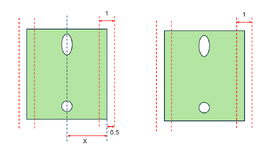
But I guess what I don't fully understand, if I had let's say a block with datums ABC being a plane, hole and slot, all of them prequalified. Then a surface profile of 1 on the general notes. The left one being controlled back to the datums and the right one to no datums. In the end, the tolerance zone wouldn't be the same since the right one is from nominal and the part would need to kind of "best-fit" with that surface profile of 1? What am I missing here? :)
1740146542223.png
 
A couple of things going on here.... Profile of a surface related to datums always controls form and orientation (unless "T" is given, which nullifies form, but that's rare). It may also control size, and it will do that if a general profile is given for the drawing, as the OP indicated.
Profile relative to a datum might control location too, if the relationship between the surface and the datum reference frame is given with basic dimensions. But that's not required, as shown in Fig. 11-32 of the 2018 standard (not sure why that figure always gets people worked up).

That being said, if there is a general profile note that captures the entire part, then size, form, orientation, and location are controlled because all surfaces are toleranced simultaneously, meaning they are also tied to each other automatically.
 
Isn't it profile with datums contoling shape, size, orientation and location, as mentioned above, and without datums same but no location?

But I guess what I don't fully understand, if I had let's say a block with datums ABC being a plane, hole and slot, all of them prequalified. Then a surface profile of 1 on the general notes. The left one being controlled back to the datums and the right one to no datums. In the end, the tolerance zone wouldn't be the same since the right one is from nominal and the part would need to kind of "best-fit" with that surface profile of 1? What am I missing here? :)
View attachment 5261
In the case of no datums, the part could be best-fit to the whole structure of tolerance zones. In the case of a datum reference frame, the part can only be aligned by the appropriate rules to the datum feature simulators, relative to which the tolerance zones are fixed at basic, and that would be more restrictive.
 
In the case of no datums, the part could be best-fit to the whole structure of tolerance zones. In the case of a datum reference frame, the part can only be aligned by the appropriate rules to the datum feature simulators, relative to which the tolerance zones are fixed at basic, and that would be more restrictive.

But then, on my example above, aren't the tolerance zones the same on those surfaces for a surface profile with datums and with no datums? like couldn't both surfaces on both figures be anywhere in between the red dashed lines?


Profile relative to a datum might control location too, if the relationship between the surface and the datum reference frame is given with basic dimensions. But that's not required, as shown in Fig. 11-32 of the 2018 standard (not sure why that figure always gets people worked up).
I never paid attention to that figure, I wonder, if the control was 0.07 |A|B| surface of a profile instead of surface of a line, with the 80+/- 0.2 size tolerance still in place, would that be indirectly controlling the flatness of datum A by 0.33 (0.4 size - 0.07 surf profile)?
 
The tolerance zones are indeed the same,
But the actual part-to-tolerance-zones relationship will be different between the two cases because in one case the part will be forced to align with the datums (and the tolerance zones are basically located and oriented from those datums) and in the other case you can consider the structure of tolerance zones to be free-floating relative to the part, which enables you to find a fitting condition that minimizes the measured value of profile or even accept a part that could be rejected when evaluated relative to datums.
 
Got it now, with that wording I understood. I knew I was missing something but couldn't picture what. Thanks!
 
I never paid attention to that figure, I wonder, if the control was 0.07 |A|B| surface of a profile instead of surface of a line, with the 80+/- 0.2 size tolerance still in place, would that be indirectly controlling the flatness of datum A by 0.33 (0.4 size - 0.07 surf profile)?
Yes, it would be controlling flatness (and parallelism, and perpendicularity). But not size and not location. So that's an example of the profile symbols referencing datums yet not doing location.
It is by far more common to have profile linked to its datums with basic dims, though.
 
Frokilin,
You mentioned that the part has a plane-hole-slot datum feature structure and that the features have been prequalified (I will assume here that the prequalification means that the primary planar datum feature meets its flatness tolerance, secondary hole meets its size and perpendicularity relative to A, and tertiary slot meets its size and position tolerance relative to A|B). Maybe this is obvious, but in such a case a general profile with no datums applicable to all remaining features of the part will have one significant problem compared to the case with a general profile to A|B|C used - the remaining features will not be controlled for orientation and position to the A|B|C datum reference frame (DRF). This is not acceptable from the definition completeness point of view.

Theoretically, the part could have no datums at all and every feature of the part, including the datum features, might be controlled with a general profile with no datums from the general note, but then a philosophical question might be asked if this way of defining profile requirement would technically be a pattern/group creation mechanism, thus if it would be "strong" enough to impose mutual relationship between the features. Note that the definition of pattern given in para. 3.44 in Y14.5-2018 does not list "datumless-profile-specified-in-general-note" as a grouping mechanism. So to mitigate the risk, the general note would need to clearly say that the profile requirement applies to all part features simultaneously.

Regarding fig. 11-32, it's bad that this figure is in the standard. The key problem with it is that it arbitrarly (that is, without any specific indication on the face of the drawing) dictates that the datums used in the line profile tolerance are just for orientation and not location. This issue becomes apparent in the attempts to achieve automated downstream consumption of annotations (for example, in MBD world). I will take a risk and say that today no software in the world is able to automatically recognize, without a human intervention, that the directly toleranced dimension and the profile requirement are related with each other. As a consequence, the software will simply treat the two requirements independently and the line profile tolerance of 0.07, due to the presence of a datum reference from which location of the line elements can be established (datum A), will be treated as a location tolerance.
 
Last edited:
Regarding fig. 11-32, it's bad that this figure is in the standard. The key problem with it is that it arbitrarily (that is, without any specific indication on the face of the drawing) dictates that the datums used in the line profile tolerance are just for orientation and not location.
It's not arbitrary; one simply has to look at how the surface (well, line) is related to the datum. And in that case it's not a basic dimension, so we are to understand that it's doing the lower-level control of orientation. That's the specific indication that you're looking for.
I'm sure that you agree that if the symbol in Fig. 11-32 were profile of a surface, it would be identical to using the angularity symbol.

And, although I don't know much about the MBD aspect, why would it be confusing to have profile relate to its datums with toleranced dimensions? It complies with the concept of profile (which, after all, is a bit of a chameleon), so I'd say that it's the software's fault that it can't understand GD&T.
 
Thank you both for your replies. Where in the 2018 standard implies that the surface profile controls location only when there is a basic dimension? I can't find it.


Note that the definition of pattern given in para. 3.44 in Y14.5-2018 does not list "datumless-profile-specified-in-general-note" as a grouping mechanism. So to mitigate the risk, the general note would need to clearly say that the profile requirement applies to all part features simultaneously.
I guess using the "all over" from that paragraph should work in that case. But, personally, I a trying to convince the designers to have the general profile note called out back to the ABC datums.
 
Frokilin,
Check the definition of "true profile". True profile for profile is like the "true position" for position - it is what locates and orients the tolerance zone it must be basic dimensions in one form or another; either on the drawing or model data.
 
But like True positions implies "the theoretically exact location of a feature of size, as established by basic dimensions"
The True profile doesn't relate the location to a basic dimension?
 
" true profile: the profile defined by basic radii, basic angular dimensions, basic coordinate dimensions, basic dimension of size, undimensioned drawings, formulas, or mathematical data, including design models."

Yes, It doesn't mention "location" but it is clear from that definition that once a dimension is not basic it is not part of a true profile. So if a true profile is of undefined location from the datum reference frame (beause of no basic location dimensions) it can't be used to control location. Hope it makes sense.
 
The model is considered basic. This should be part of the default profile tolerance note [edit] along with ALL AROUND after the profile FCF [/edit].
 
" true profile: the profile defined by basic radii, basic angular dimensions, basic coordinate dimensions, basic dimension of size, undimensioned drawings, formulas, or mathematical data, including design models."

Yes, It doesn't mention "location" but it is clear from that definition that once a dimension is not basic it is not part of a true profile. So if a true profile is of undefined location from the datum reference frame (because of no basic location dimensions) it can't be used to control location. Hope it makes sense.

I'll disagree a bit. Paragraph 3.68 defines true profile as requiring basic dims to define the profiled feature itself. It does not mention anything about the feature's relationship to any datums.
If a DRF is imposed but the location dimension to the profiled feature is not basic, then it controls orientation (with the angle being implied basic).
 
Last edited:
Got it. As mentioned above if the note "model is basic" that would mean no basic dimension is needed for the surface profile to control the location? is that on the Y14.41 standard (I don't have access to it) mentioned in paragraph 5.1.1.2 (d) : "Basic dimensions shall be indicated on the orthographic views or in the model in one of the following ways: (d) specifying and querying basic dimensions on models. See ASME Y14.41" ?
 

Part and Inventory Search

Sponsor