Eng-Tips is the largest engineering community on the Internet

Intelligent Work Forums for Engineering Professionals

  • Congratulations waross on being selected by the Tek-Tips community for having the most helpful posts in the forums last week. Way to Go!

Pump A discharge line merging downstream with pump B discharge line 1

Status
Not open for further replies.

unclebensrice

Petroleum
Oct 1, 2010
44
0
0
GB
Dear all,

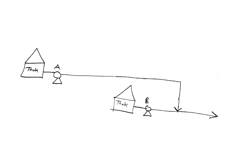
Whenever Pump B comes online, pressure on Pump A goes up and trips it. is there anything that can be done to resolve this? both pumps need to be working simultaneously.

thanks.

sketch_omtp9g.jpg
 
Replies continue below

Recommended for you

Make Pump A bigger / higher head / variable speed?

Throttle pump B and slowly increase flow up to whatever limit is casuing Pump A to trip.

What does Pump A trip on?

Install two lines?
Make the pipe bigger?

I mean give us some data please, such as flow rates, pump curves, pressures, lengths, diameters, fluids....

What are the limiting conditions here?

Remember - More details = better answers
Also: If you get a response it's polite to respond to it.
 
Assuming these are centrifugal pumps?
What is triggering the shut down of pump A, a pressure switch?


It is a capital mistake to theorise before one has data. Insensibly one begins to twist facts to suit theories, instead of theories to suit facts. (Sherlock Holmes - A Scandal in Bohemia.)
 
yes both pumps are centrifugal

data taken from pump curves:

BOP:

pump A Data is: 350 gpm @ at 370 ft head

pump B data is: 1225 gpm @ 295 ft


I believe the system curve intersects at the above points.


pump A trips on a pressure switch

fluid is oil but the pump design utilized bernoulli's equation

they're proposing installing a control valve but what is that gonna do its just gonna remain open

final solution is to separate the lines but is their anything else that can be done

i was thinking maybe a minimum flow bypass line on pump A's discharge but i dont know

thanks.


limiting conditions are

pumps can't be replaced too expensive
line cannot be made bigger too expensive
even separating the lines might not be done due to cost

is there a simple fix ?

so you're syaing if i throttle pump B just enough not to trip it that would lower the system pressure on pump A thus allowing more flow from Pump A ?


Pump A is tripping because total head now being generated due to addition flow thru' the system, you need to re-set the pressure switch to account for the increased pressure.

The head increases as Q^2

It is a capital mistake to theorise before one has data. Insensibly one begins to twist facts to suit theories, instead of theories to suit facts. (Sherlock Holmes - A Scandal in Bohemia.)
 
Uncle Ben,

Please post the pump curves and the system curves if you have them.

Little snap shots of data don't help us.

Start with operation of pump A - pressure at the pump, pressure at pump B and flowrate
Then advise pressure when Pump B comes on line.
what is the pressure switch set at?
Pipe sizes and lengths would help plus what the conditions are at the far end? A fixed pressure or pumping into another tank or?

Pump B looks like it is backing out pump A, but normally a pressure trip on a centrifugal is not a great plan when feeding from a tank as you can only have a certain max head coming in.

but yes, if the issue, which is what it looks like, is that pressure drop in the line from pump B down is too high for both flows, then reducing flow from Pump B is a potential solution.

Remember - More details = better answers
Also: If you get a response it's polite to respond to it.
 
Those seem to be pump rating points.
You end to know actual discharge pressures of the pumps.
Actual flows through each pump would help too.
What line diameters and lengths?
Elevations, if different.
You need to post all the known information.

 
If you have limited funds, the simple solution is to throttle the pumps back. If you are operating with pump B at 1225 gpm, then throttle both pumps back to a combined flow of 1225 gpm. The combined flow is probably only 10% higher than that anyway.
 
attached are the pump curves

elevation is flat

final destination is a tank

the supervisor mentioned that every time pump B came on line he had to physically go to the site and throttle a gate valve to keep pump A working. I'm not sure where the location of that valve is on the lines. I'm not an operations guy im not even a design guy they just asked me to help im in material inspection.

Anyways the supervisor mentioned he would like to replace the gate valve with a control valve. would it be a flow control valve or a pressure control valve


let me find out what valve he's talking about and then I'll get back to you guys.

pump_A_curve_ey2jku.jpg
pump_B_curve_cky5p0.jpg


those BOPs on the curve are based on the system curve at the given BOP flow rates on the pump curves so 1575 gpm total for both pumps is what i think is happening
 
The increase in flow when both pumps are operating is causing the headloss to increase in the piping where the flow is combined.

Throttling the valve is reducing the flow and headloss.

You need a flow control valve to make it operational. Maybe not the best solution based on existing equipment, economics, or operational aspects.

The only method to understand the pumped system is to calculate the system headloss.

 
If the pressure on pump A goes to 190 PSI then there is zero flow from the pump as it exceeds is head capability.

It would seem that pump B is way oversized if you need flow from pump / tank A

It is a capital mistake to theorise before one has data. Insensibly one begins to twist facts to suit theories, instead of theories to suit facts. (Sherlock Holmes - A Scandal in Bohemia.)
 
ok so the gate valve i was telling you guys about is located on Pump A's discharge and it is somewhat throttled when pump B is off . So now when pump B comes on, the supervisor runs down to pump A's gate valve and opens it fully then everything goes back to normal with respect to the two pumps. this happens like every hour or so and its a huge hassle. The supervisor is would like a control valve in place of the gate valve. is this the solution ?
 
I was wondering about that.

As you've not told us diameter, operating lengths etc it's impossible for us to work out what is going on exactly.

BTW what is this stuff you're pumping? The data sheet for pump A quotes an SG of 1.14, a viscosity of 200cP(!) and a dreadful efficiency of 31% It doesn't sound like "oil" to me...
Is pump B pumping the same stuff?
190 psi at an a SG of 1.14 gives me 380 ft head on pump A which seem well within its capability. There's something amiss with the data here IMHO

So this sounds like pump A left on its own would shoot off the end of the curve and trip on something - vibration, high temp etc - because the flow resistance in the pipe is too low for it.
Or even then, without proper monitoring of pump A standalone operation is it operating off the curve even with the gate valve partly shut? What is the operating pressure / flow when it works on its own?

So Operations as usual have found a nifty trick which will destroy the gate valve to make it work.

So yes, a control valve controlling on flow to limit flow from pump A to 350-400 GPM will do the trick and allow the changes when pump B comes on line to be accommodated.

There is no difference between a "flow control valve" and a "pressure control valve". It's just a Control Valve and how it functions just depends on what you decide to make it control on. In this case flow.

But you really need to get some proper data before you work it out.


Remember - More details = better answers
Also: If you get a response it's polite to respond to it.
 
It would appear this was a very poorly perceived idea from day one that is now trying to be rectifies using incorrectly selected equipment - - band aid solution comes to mind.

The cure is to re-engineer the whole installation using an intelligent engineering approach, not trying to rework inefficient over performing pumps pumps that have shown to be not suited for the application.


It is a capital mistake to theorise before one has data. Insensibly one begins to twist facts to suit theories, instead of theories to suit facts. (Sherlock Holmes - A Scandal in Bohemia.)
 
I agree, but that's how it goes sometimes. Operators will find all sorts of ways to "make it work" which you would never normally think about, but they have an overriding desire to do that.

But that's why design engineers exist - to design stuff that works properly, efficiently and with the least amount of hazard.

UncleBen would be best advised to get an experienced engineer involved, but it sounds like he's been lumped with it....

Remember - More details = better answers
Also: If you get a response it's polite to respond to it.
 
😊 but operators don't pick up the excessive power, maintenance, lack of production, and labour bills to keep the inefficient operation running.

It is a capital mistake to theorise before one has data. Insensibly one begins to twist facts to suit theories, instead of theories to suit facts. (Sherlock Holmes - A Scandal in Bohemia.)
 
Status
Not open for further replies.
Back
Top