Continue to Site

Eng-Tips is the largest engineering community on the Internet

Intelligent Work Forums for Engineering Professionals

  • Congratulations KootK on being selected by the Eng-Tips community for having the most helpful posts in the forums last week. Way to Go!

Rafter without fly brace? 22

Status
Not open for further replies.

fourpm

Industrial
Oct 12, 2019
13
I am designing rafters to AS4100 and wondering what if I don't use fly brace. I understand that with fly brace it will give you full restraint. But if I don't use fly brace, will the purlin above be considered as lateral restraint for rafter under uplift? If so. can I take the purlin spacing as segment and the only factor that changes without fly brace is kt?
I have the same question when it comes the continuous steel floor beam design where Z/C floor joints sit on top of the beam. What segment should I take for the beam near the support? Can I take the floor joists spacing as segment with lateral restraint? Can anyone give me some examples? I have read some manuals but the examples they have are simply supported beams only. Thank you.
 
Replies continue below

Recommended for you

An interesting discussion. I had a reply mostly typed up a couple of days ago but must have gotten distracted with work.... As well as being difficult to justify why you can just reduce the effective length simply because there is a moment inflection. An important bit to remember is that with live load you don't know where that moment inflection will be.


As an aside. I've been looking at fly brace economies and they don't seem that cheap where access is more difficult. Counting the number of members that need to be fabricated and installed and you can quickly find that going for a heavier section beam might work out in your favour. Of course cost of labour etc varies on region.
 
I'll elaborate on all of this stuff in a second post but, to begin with, the following.

Tomfh said:
This is certainly a safe approach, however quite conservative as it ignores the restraining effect of the floor against lateral torsional buckling.

I would characterize the approach as:

1) Appropriately conservative and;

2) The only, rational approach that can be shown to be safe.

Tomfh said:
My reading of AS4100 is that you can treat restraints on the compression flange as lateral restraints, which reduces your effective length.

Agent666 said:
I concur, this is the intent of the 'L' restraint, provided you are preventing via external means deflection of the critical flange. It can rotate, but no lateral deflection of the flange.

I believe that you're both incorrect in that interpretation on the basis that the bottom flange is the critical flange and therefor the [L] restraint provided by the floor joist is not efficient in restraining negative moment LTB (lateral torsional buckling).

Tomfh said:
What I find a bit murky...Is that the intent you think? Is it saying that in such a location you can happily restrain either top or bottom and achieve an L restraint.

3) I don't believe that is the intent.

4) Regardless of the intent, I'm confident that interpretation is out of step with fundamental, LTB stability principles.

5) I think that I can de-murkify this by adding some custom commentary to the AS4100 provisions based on the fundamentals. Next post.

My feeling is that the way AS4100 is set up for LTB tends to cause designer confusion in instances where there is moment reversal within a segment/sub-segment. I sympathize.
 
So here's how I think that this should be approached with respect to AS 4100 LTB provisions. Please keep in mind that my access to the standard is limited and outdated. Patience and understanding...

1) I think that it's critical to recognize that, with moment reversal, the design effort has to bifurcate into two paths:

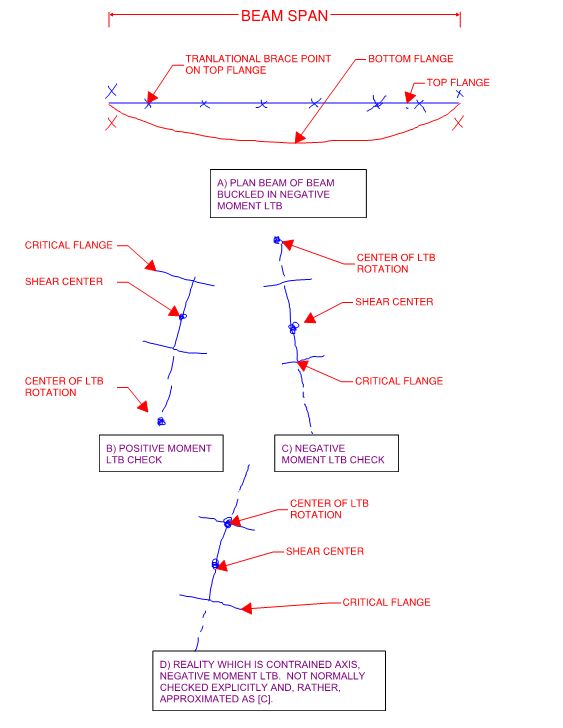
a) LTB rotation about a point in space below the shear center which is used for the positive moment / top flange check (sketch B below).

b) LTB rotation about a point in space above the shear center which is used for the negative moment / bottom flange check (sketch C below).

Recognizing this bifurcation is important because, for the two paths, both of the following may be different:

c) the definition of the "segment". Going forward, I'll use "segment" as being equivalent to "segment/sub-segment".

d) the definition of which flange is the critical flange. (foreshadow hint: it's always the flange furthest from the center of LTB rotation).

Path [a] is trivial for OP's situation given the tightly spaced, translational bracing [L-bracing]. As such, everything that follows pertains to path , negative moment LTB.

2) For negative moment checking, it must be recognized that the bottom flange is the critical flange. As shown in sketch [A] below, it's the only flange capable of meaningful lateral movement.

3) For negative moment LTB checks, "segment" = "distance between beam supports" which I assume are fully braced such that both flanges are effectively, if indirectly, braced against lateral translation. "segment" <> the spaces between joists because, for negative moment LTB, the transnational restraints provided by the floor joists do not provide efficient translational restraint to the bottom flange which is the critical flange.

4) Because "segment" = "distance between beam supports" for the bottom/critical flange, the entire bottom flange must be considered to be the "compression flange" for the purpose of negative moment LTB checking. This is not changed by the fact that the bottom flange is not in compression, and is in fact in tension, over some of its length. Viewed this way, I believe that this addresses Tomfh's "murky" problem because the bottom flange is now both:

a) The flange that would experience the most lateral translation under unrestrained, negative moment LTB checking and;

b) The compression flange under negative moment LTB checking.

5) This winding road takes us back to "unbraced LTB tength" = "span between supports" for the negative moment check.

6) As shown in sketch D below, our real world expectation is actually constrained axis buckling about the top of the beam. This usually has a higher capacity than sketch C but is a serious pain the the butt to calculate so we just go with sketch C and call that good enough.

c02_mbbdbu.jpg
 
Kootk said:
I believe that you're both incorrect in that interpretation on the basis that the bottom flange is the critical flange and therefor the [L] restraint provided by the floor joist is not efficient in restraining negative moment LTB (lateral torsional buckling).

Floors are good at preventing overall lateral torsional buckling of continuous beams. A continuous beam with a floor attached to the top flange has a much higher buckling load than a beam with no such restraints.

Presumably that’s why AS4100 allows you to take the compression flange as the critical flange.

 
kootk said:
I believe that you're both incorrect in that interpretation on the basis that the bottom flange is the critical flange and therefor the [L] restraint provided by the floor joist is not efficient in restraining negative moment LTB (lateral torsional buckling).

Maybe I'm getting the wrong end of the stick here, but I thought we were talking about the first joist into the positive moment region after a negative moment region so the top flange (the one in compression and being restrained at the point of restraint) is the critical flange? Totally agree with what you are saying if the original poster meant the first joist in the negative moment region where the bottom flange is in compression. An 'L' restraint to the non critical flange is basically 'nothing' with respect to restraint in terms of NZS3404 & AS4100.

EDIT, this is what was said, first joist in the positive region, as we'd interpreted it?
OP said:
I will take the first floor joist outside each injection point in positive moment area as the segment length for negative moment capacity check.

A sketch from OP would help here!

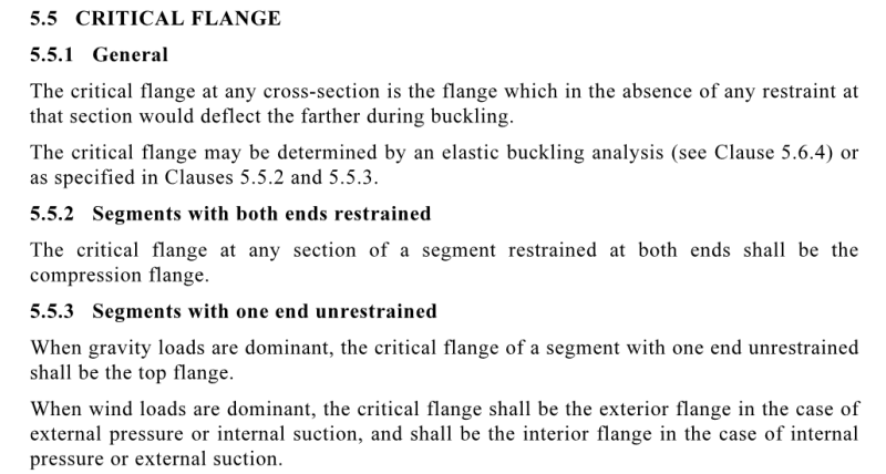
To those of you noting the AS4100 definition is a bit wonky, take a look at the definition in NZS3404, it attempts to clarify the non compression flange being the critical flange in some instances.
 
agent666 said:
Maybe I'm getting the wrong end of the stick here, but I thought we were talking about the first joist into the positive moment region after a negative moment region so the top flange (the one in compression and being restrained at the point of restraint) is the critical flange?

Yes we are talking about the first joist in the positive moment region, ie where the top flange goes into compression.

Kootk is saying that the bottom flange will deflect the farthest in the unrestrained situation even in the positive moment region (he is correct about that), and he is saying therefore that the top flange can never be considered the critical flange(since it never buckles further than the bottom flange), and therefore it can’t count as a lateral restraint point. This is where our opinions part ways.

AS4100 says we may take the compression flange as the critical flange, which is suspect is the codes way of recognising that floors etc do indeed provide reliable resistance against buckling.

So the argument here is down to whether the top flange may be considered the critical flange in the positive moment region. You and I (and I believe AS4100) are saying yes. kootk is saying no, hence him saying the effective length is 8m

Any chance you could post the NZ3404 definition?
 
As far as I can tell who cares whats going on between the restraints, the restraint clarification is only based on the location of the restraint.

Having said that the critical flange is strictly defined as the flange which moves the furthest in the absence of the restraint. To determine this for sure you need to do some buckling analyses. So totally impractical for day to day design. But I see where the discrepancy is coming from now.

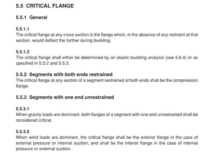
In terms of applying this for practical design (Keep in mind these provisions are from NZS3404 and the last time I looked at it in another thread a while back there were subtle differences when compared with AS4100), basically for the purposes of defining the critical flange for a segment with restraints at both ends the code says it is simply taken as the compression flange, end of story.

Annotation_2019-10-19_112055_ammswh.png


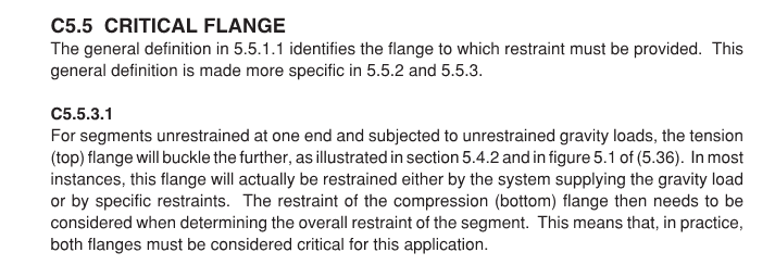
Edit - Commentary clause to go with this

Annotation_2019-10-19_112245_b0kuk8.png
 
Agent666 said:
To those of you noting the AS4100 definition is a bit wonky, take a look at the definition in NZS3404, it attempts to clarify the non compression flange being the critical flange in some instances.

If anybody would be willing to post snips of either the AU or NZ definitions on this, that would be peachy.

EDIT: my dream has come true...

Tomfh said:
Kook is saying (correctly) that the bottom flange will deflect the farthest in the unrestrained situation, and he is saying therefore that the top flange can never be considered the critical flange(since it never buckles further than the bottom flange), and therefore it can’t count as a lateral restraint.

Not too shabby. I'll try a quick and dirty summary myself:

1) Assume fully braced (F) supports each segment end and only top flange, transnational only braced points in between (L).

2) For negative moment LTB checks, no top flange bracing will make a lick of difference to calculated capacity no matter where it's placed. The only exception is if one gives detailed consideration to constrained axis LTB which, to my knowledge, is not a part of anyone's base code/standard/software.


Agent66 said:
Having said that the critical flange is strictly defined as the flange which moves the furthest in the absence of the restraint. To determine this for sure you need to do some buckling analyses. So totally impractical for day to day design.

Or you could just follow this simple procedure.

KootK said:
1) I think that it's critical to recognize that, with moment reversal, the design effort has to bifurcate into two paths:

a) LTB rotation about a point in space below the shear center which is used for the positive moment / top flange check (sketch B below).

b) LTB rotation about a point in space above the shear center which is used for the negative moment / bottom flange check (sketch C below).

Tomfh said:
AS4100 says we may take the compression flange as the critical flange, which is suspect is the codes way of recognising that floors etc do indeed provide reliable resistance against buckling.

Agent666 said:
basically for the purposes of defining the critical flange for a segment with restraints at both ends the code says it is simply taken as the compression flange, end of story.

Yes, the critical flange here will be a compression flange. The trouble, I believe, is with the definition that you guys are using for what is a compression flange.

KootK said:
4) Because "segment" = "distance between beam supports" for the bottom/critical flange, the entire bottom flange must be considered to be the "compression flange" for the purpose of negative moment LTB checking. This is not changed by the fact that the bottom flange is not in compression, and is in fact in tension, over some of its length.

For the negative bending checks, the bottom flange is the compression flange in this context, even in the middle where the moment is positive. It is a strut subject to compression and compression buckling over a length equal to the span between supports.
 
agent666 said:
Having said that the critical flange is strictly defined as the flange which moves the furthest in the absence of the restraint


Yes. And this is generally not the top compression flange in these types of situations. The bottom flange buckles the most within the positive bending zone.

Yet for practical design purposes (no buckling analysis) the code says take the compression (top) flange as the critical flange. This contradicts the “flange which moves furthest” premise.


Thanks for supplying NZ3404. It seems essentially the same?
 
kootk said:
2) no top flange bracing will make a lick of difference to calculated capacity no matter where it's placed

These codes allows you to take the compression flange as a critical flange (clause 5.5.2), which reduces effective length and thus enhances capacity.

Rational buckling analysis also show significantly enhanced buckling capacity with restraints on the top flange.
 
Here are the AS4100 provisions for comparison Kootk:-
1_qzi2ed.png


2_vurimw.png


The definition of what is the compression flange is simply the flange under compression due to flexure at the location of a restraint.

I.e. nothing in between in terms of the moment distribution matters, nor does axial load (dealt with separately via combined actions checks and the like), the moment distribution is taken care of by the alpha_m factor, similar to Cb factor in AISC.

All the restraints give you as a factoring up or down of the length to give an equivalent effective length over which buckling occurs.
 
Thanks for posting the 4100 commentary.

It’s strange that it refers to 5.5.2 as being a “more specific” version of 5.5.1, when in reality 5.5.2 contradicts 5.5.1. I’d thought 5.5.2 was an override of 5.5.1 rather than a refinement of 5.5.1

If you follow 5.5.1 then you can’t count a laterally restrained top flange anywhere (which is what kootk is arguing). But if you follow 5.5.2 you can use a laterally restrained top flange when it goes into compression, which is what pretty much everyone does, and what the design packages do.
 
Agent666 said:
basically for the purposes of defining the critical flange for a segment with restraints at both ends the code says it is simply taken as the compression flange, end of story.

Right, but to view "compression" flange in the correct fashion, you first have to view "segment" in the right fashion. In our case, it plays out like this for negative bending LTB checking:

1) "segment" = the bottom flange between the beam support points where there is full rotational restraint.

2) "compression flange" = the bottom flange, spanning from support to support, because:

a) that is the flange that moves the most during bucking (constrained axis buckling about the top flange) and, practically, is the only flange capable of moving here and;

b) the bottom flange has compression in it over the length of the segment which is not changed appreciably by the fact that the level of compression varies across the segment.

Once "segment" is viewed properly, all of the provisions become internally consistent which, frankly, ought to be taken as something of a sign.

Agent666 said:
The definition of what is the compression flange is simply the flange under compression due to flexure at the location of a restraint.

Note that, with segment properly defined, the bottom flange satisfies this definition.

Thanks for posting the AS4100 stuff, that's a great help.
 
Tomfh said:
..and what the design packages do.

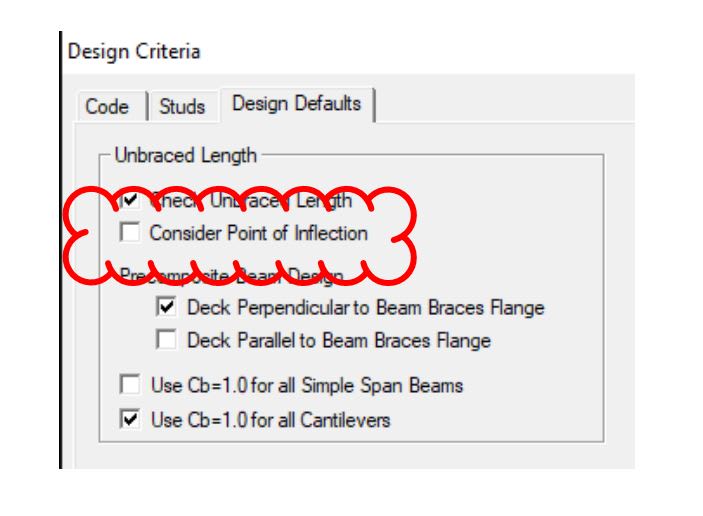
I'd not put much stock in that. The clip below is from an older version of RAM S-Beam. Software follows designer practices rather than leading them.

c01_ldxawi.jpg
 
Tomfh said:
Rational buckling analysis also show significantly enhanced buckling capacity with restraints on the top flange.

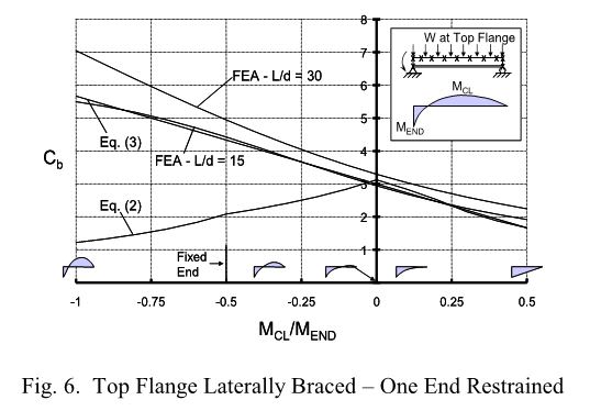
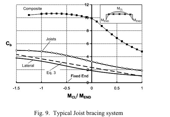
Yes, they do. The graphs below quantify that effect for any interested parties. Cliff notes:

1) EQ2 is the north american version of the moment gradient.
2) EQ3 is a modified version of EQ2 suggested for when inflection points occur within a segment.
3) Fig6 quantifies the improvement associated with having inflection points within a segment.
4) Fig9 quantifies the benefit accrued from the slight rotational restraint supplied by a typical joist seat connection.

So, yes, there absolutely are improvements associated with these things. From my perspective, the question really becomes:

A) Do we qualitatively take these things to simply mean that the buckling mode shown in the last sketch below is impossible/impractical OR;
B) Do we use a Cb based approach to rationally asses the buckling mode shown in the last sketch below?

For me, it's path B without question.

c01_dlbk1i.jpg


c02_mnzjld.jpg


CO3_ap3oor.jpg


c04_djjmix.jpg


c05_kmfh3r.jpg
 
Kootk, at the middle of the beam the top flange is in compression. At any section of the beam the code allows you to take the compression flange as the critical flange.
 
Tomfh said:
Kootk, at the middle of the beam the top flange is in compression. At any section of the beam the code allows you to take the compression flange as the critical flange

a) I wholeheartedly believe that you are misinterpreting that code provision and;

b) At the end of the day, I don't care what any code says. A first principle understanding trumps all else for me.

In fact, I believe that it is the lack of a first principle understanding on this that is leading you and Agent666 astray.

Tomfh said:
What I find a bit murky is AS4100 initially defines the critical flange as the flange which will deflect the furthest if the beam was fully unrestrained, however it also allows you to simply take the compression flange as the critical flange.

Is that the intent you think? Is it saying that in such a location you can happily restrain either top or bottom and achieve an L restraint?

Frankly, your stance on this confuses me. You yourself clearly question either:

a) What the code says and/or;
b) Your interpretation of what the code says.

Given that, I don't understand your dogged resistance to my alternate interpretation.


The code says you can take the compression flange to be the critical flange. The "compression flange" is invariably understood to mean the flange in compression, which is the top flange in the positive bending zone in our example.

Allowing the use of the compression flange contradicts the code’s original definition of the critical flange (the flange which buckle farther), because sometimes the compression flange does not deflect the furthest, eg our example here. As you point out, the bottom flange always buckles the farthest at every point along the beam.

I can see two possibilities:

1. Compression flanges, whilst not necessarily always being the best place to brace, are nonetheless good enough places to brace that the code allows us to consider them critical flange.

2. The code is wrong allow the use of the compression flange as the critical flange, and doesn't properly consider that the compression flange isn't always critical.


You are offering a third possibility, and saying that by “compression flange” the code writers don’t actually mean the flange in compression, they simply mean the flange which will deflect the farthest, and they never intended us to use the top compression flange in examples like this one. If that’s what they mean, then reference to “compression flange” is entirely circular and redundant, as it reduces back to the original definition of critical flange as being the flange which deflects the furthest. It would also be an extremely misleading clause as most everyone understands “compression flange” to mean the flange under compression.
 
@Tomfh/Agent666,

Tomfh said:
It would also be an extremely misleading clause as most everyone understands “compression flange” to mean the flange under compression.

And indeed it is.

I have a dream. And I propose that we do it together. First I need to bash the Aussie steel code however. Please forgive me that as, no doubt, there is some national pride involved.

When I look at the Aussie steel code on LTB, this is what I see:

1) Code provisions that do a good deal more designer spoon feeding than you see in North American codes. Is that good? Bad? Prudent? Insulting?

2) On balance, I would have to say that the spoon feeding is prudent. Structural engineers are notoriously bad at stability because, frankly, the math is well above our comfort zone on average. I've worked with a wide variety of designers in Canada in the US and my experience is that mistakes get made often. And I suspect that an Aussie style spoon feeding would improve that situation a great deal.

3) In my opinion, the Aussie code falls on it's face with respect to exactly this issue: beams with inflection points. Good for simple spans; uncommonly good for cantilevers; misleading for for beams with moment reversals. The trouble with spoon feeding is that it's near impossible to make it perfectly applicable to all situations. It is, after all, an attempt to make a very complex thing simpler than it really is.

So here's my my dream:

4) I convince you guys that my way is the right way from a purely theoretical standpoint. Maybe I pull that off and maybe I don't. I feel that my odds are pretty good if you guys give me some room to run and make of point of being flexible. And, if I can't convince you guys, that will be appropriate vetting to prevent me from pursuing what would come next.

5) We attempt a rewrite of the Aussie LTB provisions to sort this out. I expect this will be quite a challenge given that a) some smart cookies obviously composed the original and b) it would require great linguistic precision and the ability to anticipate the ways in which things may be misinterpreted by designers.

6) We put our proposed rewrite in front of the Aussie steel code steering committee, whomever the heck they be.

7) For the rest of our days, we vaingloriously point to the Aussie LTB provisions and say "hell yeah, we're the dudettes that got that written properly".

Any takers?


Status
Not open for further replies.

Part and Inventory Search

Sponsor