Continue to Site

Eng-Tips is the largest engineering community on the Internet

Intelligent Work Forums for Engineering Professionals

  • Congratulations KootK on being selected by the Eng-Tips community for having the most helpful posts in the forums last week. Way to Go!

Rafter without fly brace? 22

Status
Not open for further replies.

fourpm

Industrial
Oct 12, 2019
13
I am designing rafters to AS4100 and wondering what if I don't use fly brace. I understand that with fly brace it will give you full restraint. But if I don't use fly brace, will the purlin above be considered as lateral restraint for rafter under uplift? If so. can I take the purlin spacing as segment and the only factor that changes without fly brace is kt?
I have the same question when it comes the continuous steel floor beam design where Z/C floor joints sit on top of the beam. What segment should I take for the beam near the support? Can I take the floor joists spacing as segment with lateral restraint? Can anyone give me some examples? I have read some manuals but the examples they have are simply supported beams only. Thank you.
 
Replies continue below

Recommended for you

Tomfh said:
You are offering a third possibility, and saying that by “compression flange” the code writers don’t actually mean the flange in compression...

Not quite. What I'm saying is really that you and Agent666 are misinterpreting what the code writers intended in their reference to the flange in compression. I think that what they really meant was something along these lines:

STEP 1: define "segment" for your LTB check being mindful of whether you're checking LTB rotation about a point in space above the shear center or a point in space below the shear center. For a point in space below the shear center, the segment(s) are the gaps between the joist connections. For a point in space above the shear center, the segment is the distance between the columns.

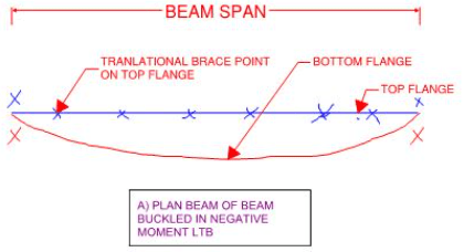
STEP 2: define "compression flange" for each segment being LTB checked as any flange exposed to compression force anywhere along its length. In the context of our negative bending check, this will make both flanges "compression flanges" for the segment defined as the bottom flange between columns. In support of this definition, see the first sketch below. Clearly, either flange could be taken as the compression flange. And that makes sense because what really matters is, just as we expect, which flange would move the most laterally. After all, it is that lateral motion that is the "buckling". The compression flange definition is, and always was, just a convenient and imperfect mnemonic to help us properly identify the critical flange.

STEP 3: define "critical flange" keeping in mind the definitions of "segment" and "compression flange" described above. Obviously, the segment that we're interested in here is the bottom flange segment between columns that will govern for a negative bending check where the point of LTB rotation is above the shear center. Following Aussie code logic, you've got two choices:

3a) define the critical flange as that which would move the most. We're all in agreement that this would be the bottom flange. Check.

3b) define the critical flange as the flange in compression. Per the definition in step 2, both flanges are in compression for this segment and this definition solves nothing. So back to 3a it is.

Viewing things this way leads to the following improvements in this situation:

1) The two critical flange definitions -- displacement vs compression - are no longer in conflict. The compression flange definition is just useless for beams with inflection points which I propose is nothing more than a shortcoming of the Aussie steel code.

2) The code writers no longer appear to be incompetent.

3) Nothing in cyclical/recursive.

These things strike me as circumstantial evidence loosely supporting my hypothesis that the code writers saw things defined as I've defined them above.

c01_qrktv0.jpg
 
@Agent666/Tomfh:

Knowing a detail of how LTB is checked in your part of the world for beams with inflection points would help me greatly here. For me, it proceeds like this:

1) If my beam has inflection points, I accept that I'll have to do two separate LTB checks.

a) LTB rotation about a point in space below the shear center. Usually this is the positive bending check where top flange faux buckling is the name of the game.

b) LTB rotation about a point in space above the shear center. Usually this is the negative bending check where bottom flange faux buckling" is the name of the game.

2) I work out the segment definitions and bracing conditions for each of the two paths, acknowledging that they may be different.

4) I do the LTB check that would have the top flange faux buckling.

5) I do the LTB check that would have the bottom flange faux buckling.

Do you guys do a similar, bifurcated check where negative bending LTB and positive bending LTB are checked separately? Or do you tackle it in a single checking procedure?
 
If you can prove theoretically that the top flange in our example may not be used as a lateral bracing point to reduce effective length then you would of course be fully justified in criticising clause 5.5.2 (or at the very least how it’s universally interpreted), as it’s precisely where designers use the clause. If you are right, maybe the clause should forbid allowing the compression flange as critical flange if moment reverses within the segment?

All that being said, merely showing that the bottom flange buckles farthest as you have been doing is a long way short of proving your case that the top flange within the positive bending zone is an ineffective point to brace, ie that designers shouldn’t be taking it as critical flange.

Remember too, the whole “critical flange” thing is just spoon feeding in the first place. In reality there’s no such thing as “critical flanges” and “non critical ages”. They’re just design rules telling designers where to brace.

If however you prove your case that means everyone is doing it wrong, and that should be rectified in the code.
 
Tomfh said:
All that being said, merely showing that the bottom flange buckles farthest as you have been doing is a long way short of proving your case that the top flange within the positive bending zone is an ineffective point to brace, ie that designers shouldn’t be taking it as critical flange.

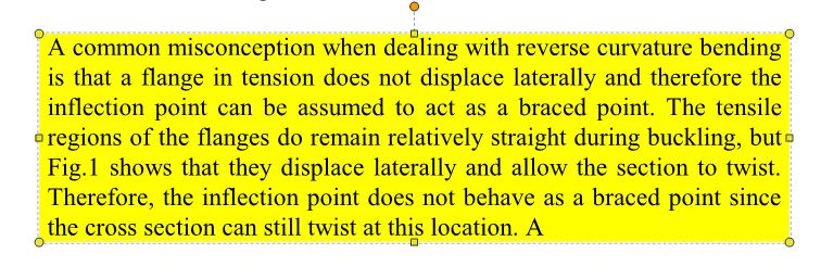
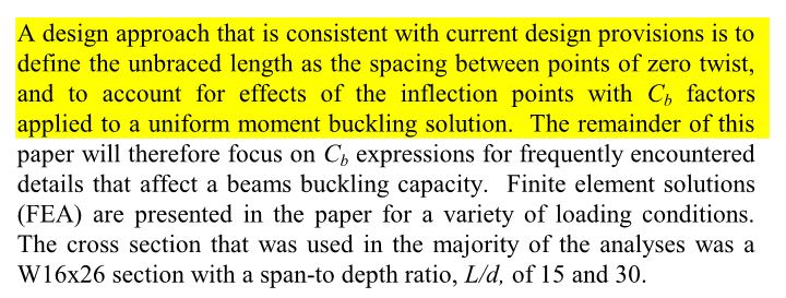
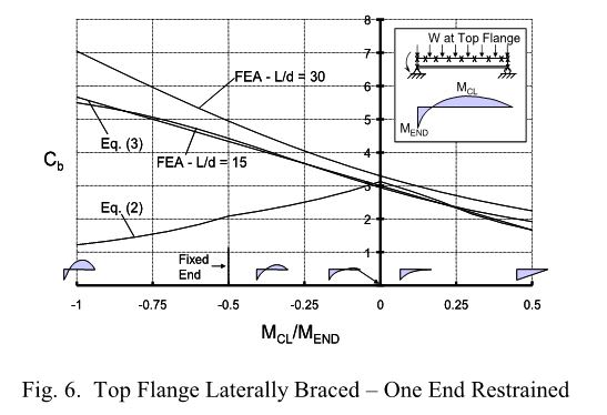
Agreed. As a next step, when you have some free time, please review the attached article by Yura. You'll find that it agrees with my stance. And that's no accident given that much of my understanding of LTB has come from reading Yura's other works. So it's a bit incestuous in that way. Still, if you digest that article and still find yourself not agreeing with my position on this, please report back so that we might reconcile our respective opinions. Who knows, perhaps all this time while I've been claiming that you've been misinterpreting your code, I've actually been misinterpreting Yura.

I've included some samples of the article below to whet your appetite for more. Among other things, they suggest the use of Cb = 1.14 as a simple way to deal with most every practical inflection point beam bracing situation out there. Good stuff. Also, while much of the article deals with designers inappropriately using IP's as brace points, the article really is about a great deal more than that. Namely, the bracing and buckling of beams with moment reversals in general.

c06_qm85bq.jpg

c01_detqys.jpg

c02_gkssbd.jpg

c03_opv4tk.jpg

c04_mpoq4s.jpg

c05_cebz7j.jpg

 
Tomfh said:
If you are right, maybe the clause should forbid allowing the compression flange as critical flange if moment reverses within the segment?

Yeah, that would be a simple fix. You've kinda made short work of what I had expected to be a difficult exercise in rewriting.
 
I will read it.

Just to clarify though, no one here is saying to the take the inflexion point as a brace point per se (as agent666’s blog shows, it provides no actual restraint), we are taking about talking about using purlins and joists BEYOND the inflexion point as lateral restraints, which is a quite a different concept.
 

Tomfh said:
..we are taking about talking about using purlins and joists BEYOND the inflexion point as lateral restraints, which is a quite a different concept.

From my perspective, these things are very similar concepts.

Concept #1: assume IP points represent full LTB brace points. False because the cross section can rotate about the shear center at such points.

Concept #2: assume lateral braces just beyond IP points represent full LTB brace points. False because the cross section can rotate about the lateral braces at such points.

#2 is obviously an improvement in that any capacity short coming will be lessened. It appears to be very much the same conceptual misunderstanding however.
 
Tomfh said:
as agent666’s blog shows, it provides no actual restraint

Interestingly, you'll find that Yura tackles the exact same scenario that Agent's blog post does. A salient takeaway from that example is that a lateral brace placed at the IP also does little to restrain LTB. More precisely, LTB is greatly improved for rotation about a point above the shear center and improved about 10% for rotation about a point below the shear center.
 
Hi All,

This is an awesome discussion, I truly am learning a ridiculous amount as a 2nd year graduate.

AS4100 is currently under revision and maybe this 'murky' clause will be rewritten or clarified. Coming out of uni, they are teaching the points that Tomfh and Agent666 are putting forward in regards to designing the critical flange as the compression flange.

What do the other design codes around the world say on this matter? Yes we've looked at AS and NZS but they might as well be the same code except for the few differences pointed out above.
 
All -

I just want to pipe in here briefly.... The concept of whether "point of inflection" should be used as a point of bracing or not is a question that I dealt with for years and years. My thoughts on the subject:

1) The software company I worked for did NOT consider point of inflection as a point of bracing. This is because of lectures from Yura and such that members of our team had attended over the years. It is now explicitly codified in the AISC codes.

2) I would speak to a number of practicing engineers who were frustrated by this. And, they wanted us to automate the point of inflection as a brace point. I would point out the code references (or the notes from stability bracing seminars that were the basis for our company's decision). They'd get annoyed at the "code geeks", "academics", or young engineers (like me at the time) who thought they knew better than them who had been designing like this for years.

3) At first, I would merely point out that they could override the default values in the program if they wished. Eventually, once I'd really researched the topic better, I would point out the same seminar notes also addressed the issue. Joe Yura (if I remember correctly) wrote in the notes, a good explanation for why the "rule of thumb" of using the point of inflection hadn't been a problem in the past and why some older engineers where so attached to it. He had pointed out that if this is done while using a Cb = 1.0, then that conservatism would negate much of the unconservatism in the unbraced length. Therefore, I would kindly suggest to the users who complained about this that if they chose to still consider the point of inflection (based on their personal engineering judgment) that they should probably check to see if the program was using a Cb of greater than 1.0. If so, then probably should use a value equal to 1.0 to offset.

I'm not an expert on what the code provisions where before the Cb factor came into use as my engineering knowledge began with the 1989 green book. However, my impression was that some of the older engineers had the attitude of "great... the code writers added lots of extra complexity with the Cb. This, in turn, requires us to add more complexity with how determine unbraced lengths for the bottom flange".


Hey Kookt,

We are back on this topic again. Which I see as a good thing as I believe there is plenty of misunderstand around. And certainly a bunch of learning for me needed. From what I can see you have are fairly on top of things, but I do have one question about one of your statements. (And I believe you made a statement of similar effect in the last thread on a simlar topic.)

Re critical flanges:
Kookt said:
a) that is the flange that moves the most during bucking (constrained axis buckling about the top flange) and, practically, is the only flange capable of moving here and;
The latter part of "practically, is the only flange capable of moving here" seems to assume the top flange is restrained which goes against the definition:
"The critical flange at any cross-section is the flange which in the absence of any restraint at that section would deflect the farther during buckling.

Your statement seems to mistinterpret the code and is a little bit recursive if you determine the critical flange in the context of existing restraints. Could you possibly elaborate? Am I just misinterpretting your statement. Thanks in advance.
 
Kootk said:
From my perspective, these things are very similar concepts.

In my opinion they are fundamentally different. An inflection point provides no actual physical lateral restraint. A lateral restraint however - whilst not providing twist restraint - nonetheless significantly inhibits the lateral component of the lateral torsional buckle. It is harder for the beam to buckle. The beam can non longer just kick out sideways.

kootk said:
A salient takeaway from that example is that a lateral brace placed at the IP also does little to restrain LTB.

I don't agree with that either. It inhibits the overall lateral component of the buckle, and forces the beam into a more difficult buckling mode. Run some buckling analyses....


Tomfh -

I agree that inflection point and brace point are two very different concepts. Though they have been (historically) mixed together in the past. I think the current codes have them pretty separate. However, in the thinking of many engineers they're similar.... Not because of first principles, but because of past design practice.

Now, we're probably getting to the point where engineers who were educated in the mid 80's or earlier may no longer be practicing. However, there are LOTS of people who worked under them for years that still conflate the two concepts. Again, not because of first principles, but because they learned under people who mixed the two concepts together.

Also, when the code calls the variable the "unbraced length of compression flange", there is an obvious reason why folks would mix the two concepts. Because the terminology suggests that when the flange ceases to be in compression, then it may not contribute to the unbraced length. Now, that's merely a terminology issue that doesn't have to do with first principles. But, I can see how that leads to confusion.
 
Tomfh said:
I don't agree with that either. It inhibits the overall lateral component of the buckle, and forces the beam into a more difficult buckling mode. Run some buckling analyses....

What's there to disagree with? Yura did the buckling analysis in the article that I provided and arrived at the conclusion that IP bracing for that example amounted to a paltry, 10% improvement. Perhaps you should run some buckling analyses and report back. So far, this is all just me digging up the quantitative stuff.

C01_dx9rba.jpg
 
kootk said:
What's there to disagree with?

It's more than 10%. But put that aside for one second - Jura says it's not effective to laterally brace a flange without providing twist restraint. He (and you) say you can only count points of twist restraint. If that's true, then AS4100 is wrong to allow lateral bracing (without twist restraint) of any flange, regardless of whether it's the critical flange. The question of which flange is the critical flange is surely a moot point if a lateral (pin) brace alone fixed to a flange is assumed to provide no reduction of effective length?
 
JP said:
Joe Yura (if I remember correctly) wrote in the notes, a good explanation for why the "rule of thumb" of using the point of inflection hadn't been a problem in the past and why some older engineers where so attached to it.

Cb = 1 surely is one reason for the dearth of consequences and dovetails nicely into the stuff in the Yura article suggesting that one could safely cover most any case with Cb = 1.14.

Along similar lines, consider:

1) When the top flange is restrained laterally, LTB is basically the bottom flange kicking sideways.

2) The bottom flange kicking sideways is substantially resisted by the bottom flange acting as a girt.

3) We assume that the bottom flange is pinned at the ends for girt action. Often, it's not.

4) We assume that the cross section is free to warp at thee ends for girt action. Often it's not.

These things introduce a lot of conservatism into the mix and aren't usually accounted for in non-FEM analyses. Basically, the only way to get a top braced, multi-span member to LTB is:

5) have adjacent spans both go critical for LTB and;

6) have adjacent spans LTB buckle in opposite directions.

That's a pretty tall order of course. My gut feel is that it's next to impossible to get a multi-span continuous beam to LTB buckle if it has full restraint at the supports and closely spaced lateral restraint anywhere on either flange.
 
Tomfh said:
He (and you) say you can only count points of twist restraint

Not quite. What we're saying is this:

1) You can only count on points of twist restraint to define the end points of the "segment" that undergoes LTB buckling. Without this, the whole thing breaks down mathematically because you lose the boundary conditions fundamental to the problem. Technically, you can go full restraint on only one end and still be in compliance but that's introducing an extra layer of fanciness that we can surely do without for this discussion.

2) You can absolutely count on points of lateral, non-twist restraint to shift the point of LTB rotation closer to the member shear center and thereby improve capacity, if not eliminate twist altogether. This is the constrained axis buckling that I must have mentioned a half dozen times by now. In terms of Yura's work, this is the graph shown below and its brethren from the article where the benefit of lateral only bracing is acknowledged and quantified.

Tomfh said:
The question of which flange is the critical flange is surely a moot point if a lateral (pin) brace alone fixed to a flange is assumed to provide no reduction of effective length?

This is an interesting question / observation. I'll attempt to answer this in my next post, in response to a question from human909.

C01_yt9cxd.jpg
 
KootK said:
Not quite.

in summary Yura says this:

Yura said:
The unbraced length that should be utilized in design should be the spacing between points with zero twist.

It seems to agree with your approach
 
KootK said:
My gut feel is that it's next to impossible to get a multi-span continuous beam to LTB buckle if it has full restraint at the supports and closely spaced lateral restraint anywhere on either flange.

Initially you said laterally bracing the top flange provides negligible increase in capacity unless you also provide twist restraint, hence your advice for OP to take 8m as the buckling length. Now you say such lateral bracing makes it next to impossible for the beam to LTB buckle?
 
human909 said:
Your statement seems to mistinterpret the code and is a little bit recursive if you determine the critical flange in the context of existing restraints. Could you possibly elaborate? Am I just misinterpretting your statement. Thanks in advance.

I believe that the confusion has come about because the Aussi-clause below is also in serious need of an overhaul. More so, actually, than even the "compression flange" business because this clause will be egregiously misleading, in a theoretical sense, 100% of the time. That it will often lead designers to make the right choice anyhow is little more than coincidence.

AS4100 said:
The critical flange at any cross-section is the flange which in the absence of any restraint at that section would deflect the farther during buckling.

I've been reticent to get into this part of things because it requires going deep, deep into the theoretical weeds of the stability swamp. Now that you've asked the question, however, it's time.

1) As designers, we tend to think that there exist a handful of buckling possibilities for any particular member and that, once those have been checked, buckling is no longer possible. This is true in a practical/functional sense but is not true in a theoretical sense. Theoretically, there are an infinite number of possible buckling modes. Like a buckling multi-verse of sorts.

2) Each possible buckling mode is associated with a particular strain energy that is required for the member to assume the proposed buckled shape. What we mean by "critical buckling mode", is the next buckling mode in the infinite series that would be associated with the lowest strain energy. As in all things, nature strives to minimize energy.

This is complicated by the fact that the intervals between different buckling modes is not uniform. The 902 nd buckling mode might require 20X the strain energy of the 901 st buckling mode. But, then, the 903 rd buckling mode might require only 1.05X the strain energy of the 902 nd buckling mode. This is why I use the dual path, bifurcated checking approach that I mentioned previously for beams with inflection points. For such beams, I can't tell by inspection whether positive bending LTB or negative bending LTB governs. So I check both. And I pray to the powers that be that the 904 th buckling mode is miles off in the distance as far as strain energy goes.

3) For the purpose of this discussion, the important takeaway of #2 is that all buckling checks must start with the designer assuming a critical buckling mode. Not knowing... assuming (hopefully based on good judgement). This is what I did with the sketch below, taken from the beginning of this thread.

4) The assumed buckling mode shape from #3 must pay homage to the physical restraints that form the boundary conditions of the problem (lateral top flange braces here). Otherwise, we're no longer discussing an LTB mode shape that has any bearing on our real world situation. Again, this is what I did with the sketch below, taken from the beginning of this thread.

5) In the AS4100 procedure, they end with finding the assumed LTB mode shape (critical flange) rather than starting with it. And, in my opinion, this is a serious mistake and is what leads to things having a recursive, chicken and egg feel to them. There's just nothing meaningful to check in the world of LTB until AFTER an LTB buckling mode shape has been assumed.

6) The AS4100 business about the "absence of any restraint" seems to lead designers to examining a case where all restraints are removed as a means of establishing the LTB buckling shape for a case when all of the physical restraints are present. How much sense does that make? None. And, in spite of the way that the provision is written, I'm sure that it's not what anyone actually intended.

7) The AS4100 provision could be revised, quite easily, as follows:

a) The critical flange at any cross-section segment is the flange which in the absence of any restraint at that section would deflect the farther during buckling given the lateral and torsional restraints present. OR;

b) The critical flange at any cross-section segment is the flange which, in the absence of any additional restraint at that section contemplated by the designer would deflect the farther during buckling. given the lateral and torsional restraints present.

Modest changes but enormous implications. It's minor but we also shouldn't be speaking in terms of "cross sections". Rather, we should be speaking in terms of "segments" because LTB is a linear phenomenon rather than a point phenomenon.

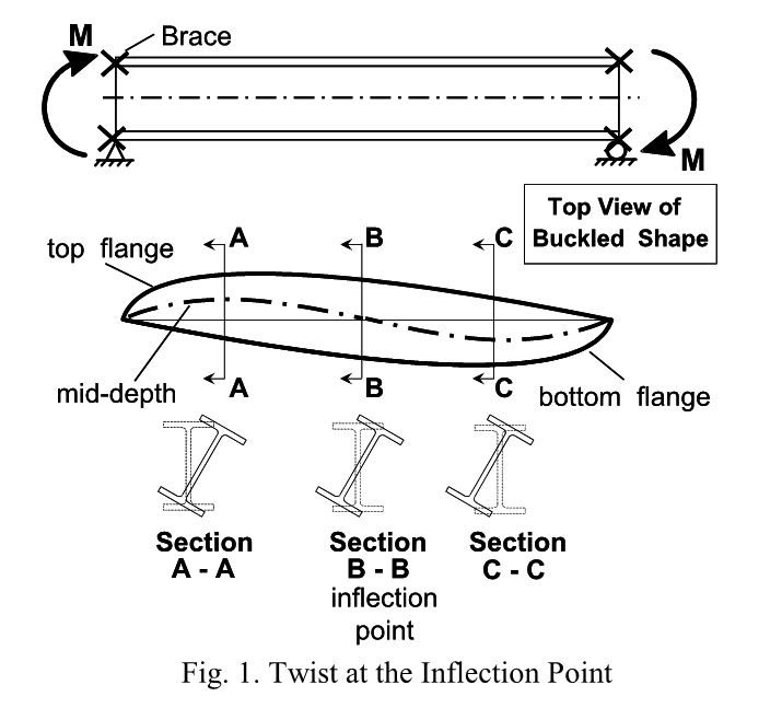
c01_xevfkq.png
 
Status
Not open for further replies.

Part and Inventory Search

Sponsor