StrEng007 - gte447f answered that question about bracing the stud. Your 'quote' of the OP (of yourself) doesn't seem to be what you actually wrote, however. It's a paraphrase.
From the top:
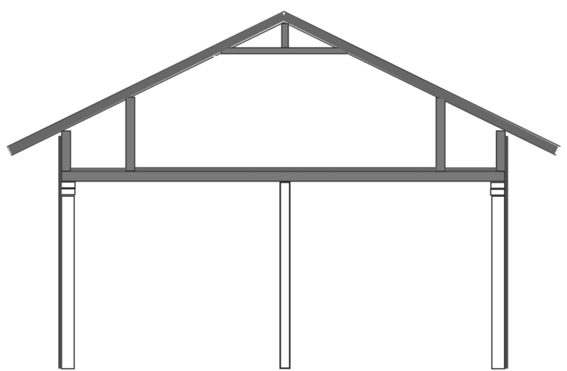
1. How important is it that my studs align with the trusses? I'm used to 16" o.c. studs, but the 24" o.c. seems to make more sense if it allows the wall panel edges to align the full height of the stud.
I'm not sure I've seen a sample calculation of a top plate bending and shear check, though it should more or less be routinely done, it's a topic that is largely skipped over. If anybody knows of calculations showing it, I'd appreciate being made aware.
Provided you check the load path, the double top plate for conventional framing (i.e. the prescriptive in the IBC and the IRC), one could argue that the spirit of the IBC is not being violated here, OR (more prudently), calculations for the top plate are necessary to ensure the stresses are sufficiently low.
How detailed one gets in a double top plate check varies widely among practitioners from:
a) no check or calculation whatsoever (engineering "judgement"), which I deeply dislike, (this is negligence, it just might not cause a failure, or the framers may add studs under the trusses and save the engineer from a collapse investigation and nobody will ever know, hence the engineer "did nothing wrong"). This is the "calculation" where the studs are 16" on center and the roof trusses are 24" on center so the stud loads are 24/16 x the truss reaction. No analysis of the top plate is performed at all. You are skipping part of the continuous load path here.
b) various presumptions about load distribution, some of which are totally unrealistic (Steimle, above, mentions some consider the (2) 2x6 as a fully composite 3" deep member, without connecting them properly for the interface shear). It simply cannot be justified as a valid approach, there aren't enough nails for that). This approach isn't valid as it isn't via "generally accepted principles of mechanics", hence it's wrong, and it's unconservative, and it's potentially unsafe.
c) Other approaches are clearly conservative (presuming the top plate is non-composite, one has a splice between the two studs and using only one in bending with zero end moments at the studs (effectively a single top plate that terminates at each stud), and the truss load midspan of the 16" or 24" space between studs. That's clearly conservative but is perhaps so conservative as to be unrealistic.
d) similar to c) above with "Adding" end moments (this is murkier, but there is some reality to it as a top plate will generally not be 16" or 24" long except in odd situations). One could also look at a single top plate, say, six feet long, or four feet (if you specify on plans), and allow a more detailed model of multiple point loads and multiple supports, still using a single top plate. Or, if the plans are more specific, perhaps a full length of the structure model that shows the cuts in the plates where you designate them, then a double top plate (non-composite) with free ends at the splices, could be entertained, I think this is equally unrealistic because either the details won't be on the plans, or it's unlikely they will be followed by the contractor.
My issue with the Steimle articles is they don't present calculations and don't take a more "that's never going to work" stance on the composite 3" deep top plate as a model.
If you have top plate bending issues, adding a stud beneath the truss is fairly common and is sometimes done along with (a). No analysis but add a stud. This may not be sufficient for very large truss reactions because the stud itself cannot take the entire load, leaving the stud buckled and the double top plate trying to resist the remainder of the load.
Overall, I'd be highly suspect of somebody trying to use the sheathing to assist the top plate because the sheathing generally is a shear wall and those nails should be saved for the lateral load.
2. Should I switch the roof truss over to 16" o.c. instead? I've got a 24'-6" clear span with an intended load bearing partition at midspan. Doing so would alleviate the close to unity wall stud but add 8 trusses to the package.
I'd expect five out of five engineers would not do this. If your approach calculates out, the load path is continuous and requirements are satisfied, the spacing has been accounted for properly and life-safety has been met. This truss is also somewhat modest span. It's possible you can get a joist design from the IRC for this span, that's part of my argument here.
3. Will the truss manufacturer be able to make use of this load bearing wall (at center) without the introduction of a vertical web?
If you designate it as a bearing wall and make sure on the shop drawings that they used it. I'm not sure it will do that much good, because that's a fairly open span and it will potentially ridge if you use that as a bearing wall. If you really want, calculate your design both ways, I kind of doubt this interior bearing wall will affect your exterior wall design, however.
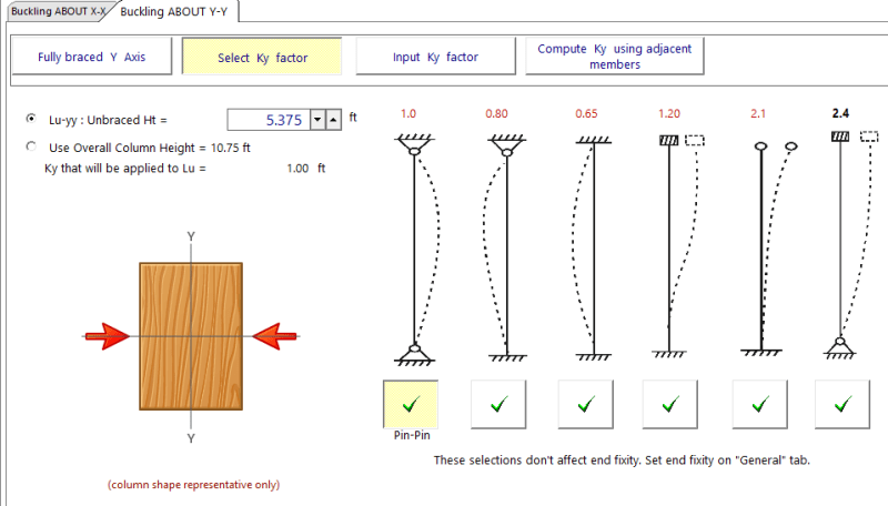
4. Is it correct to assume that my wall studs are braced full height against y-y axis buckling (axial load) if I have wood structural panel sheathing on the exterior side only? Or should this unbraced length be limited to the blocking height of the stud?
I'd say that most engineers would probably use this as braced in the 1.5" direction without even really thinking about it. You have a wood structural panel on the outside so the NDS mentions this as acceptable (gypsum board is, too, but "alternative" wall panel stuff like Therm-o-Ply aren't recognized as bracing.
Look at
4.4.1 in the 2024 NDS.
And:
3.3.3 regarding bending, and compression.
Design of Loadbearing Tall Wood Studs for Wind and Gravity Loads, American Wood Council, Showalter and Koch, circa 2017. (Youtube says 7 years ago, so I had to do math).
I'd also point you at
Design Considerations for Sawn Lumber Studs, Partain, Structure Magazine, May 2012, but I don't see the PDF link on the web site.
If you're going to consider it unbraced, I think the blocking would be considered a brace point, for positive and negative wind. There is unbraced length and effective length, however, so it's not quite so quick. I expect most engineers don't check their wall this way, but I think it makes physical sense that the sheathing on the outside is on the tension face for negative load, and the negative load tends to be larger than the positive load anyway. Application of MWFRS versus C&C loads is murkier, but using full loads and C&C wind would be simple and conservative.
5. Same thing for unbraced length due to out of plane flexure (wind load). Is my Lux considered unbraced for NEGATIVE wind if the interior stud was left unfinished (no sheathing). Is mid-height blocking good enough to cut this span in half?
I think this is the question you think isn't answered. I think gte got it, but perhaps not explicitly, but see my answer to #4 above. I feel like my impression of the NDS was a lot more "all in" on using sheathing or gypsum board as bracing the studs, the language has gotten less specific or I'm just remembering it wrong. It is perhaps in the Commentary, (
1997 NDS Commentary, view only)
Side note: I'm not sure how much good exposed insulation will do you in this scenario (mentioned earlier as "easier" with 24" stud spacing) as far as R value or heating costs. To me a lot of these R values are predicated on the whole assembly, so the gypsum board and the vapor barrier are integral to the values. I'm not an ASHRAE guy, however, that's just my first thought there. As another side note, I think pre-cut batt insulation is available for both 24" stud spacing and 16" stud spacing, so while fewer studs would reduce the framing factor and improve the R value, the labor is slightly higher (more pieces for the 16" wall), there's not that much labor lost or gained either way, and I presume 24" insulation costs more or you get fewer pieces, but whatever.
Yeah, wall of text, I know, but I'm too tired for a KootK style scribble or uploading excerpted images from the NDS.