Continue to Site

Eng-Tips is the largest engineering community on the Internet

Intelligent Work Forums for Engineering Professionals

  • Congratulations KootK on being selected by the Eng-Tips community for having the most helpful posts in the forums last week. Way to Go!

Regarding Seismic Analysis of Space frame and architectural feature 1

Status
Not open for further replies.

Arbu

Structural
Mar 25, 2018
69
Dear All,

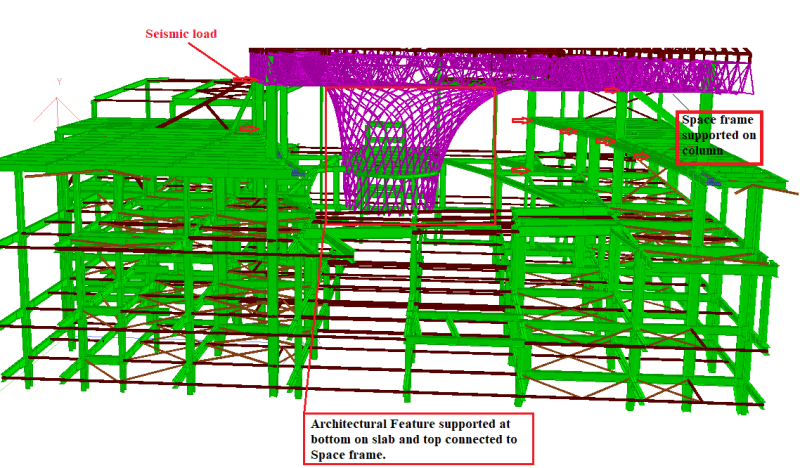
I am designing a space frame which is supported on steel columns. there is a central architectural feature as well. when I am modelling all structure in one model and running seismic analysis, then central architectural feature is taking to much load and members are failing (due to moment and compression) . The central architectural feature is made up of 114x6 mm pipes welded. Please suggest some method of modelling in STAAD such that only columns will carry lateral loads.


seismic_ikrlox.png
 
Replies continue below

Recommended for you

One other thing, your boundary conditions are perhaps not 100% realistic. If there is any vertical differential deflection between the top and bottom supports, then the loads you are getting and consequently the buckling loads might not be correct. For example if the top structure its connected to deflects vertically by 10mm, and the base 20mm, then modelling the top and bottom as fixed level supports does not accurately model the deformations your frame is potentially undergoing.
 
Dear Agent666,

Thank you for your response.
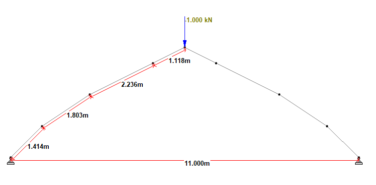
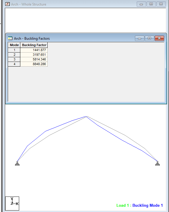
I am trying to follow your above described procedure . For a trail I considered a 11 m arch and applied a dead load of 1 kN at top ridge point. One side I considered 4 members with different lengths as shown in figure. After running buckling analysis I found a factor of 1441.877 and for 1 kN load compression in arch is 0.855 kN.


Dome_sykals.png


mode1_ohpf3v.png


therefore my buckling load for the arch will be
Pcr = 0.855 x 1441.877 = 1232.8 kN
after this I divided every beam in two parts then I found Pcr = 1231.194 kN
then 4 division per beam Pcr = 1231.055 kN.

After observing Buckling shape it has been found that le = half the length of arch. Le = 6.571 m.
then as per Euler's formula Pcr = Pi^2 x 2.05e5 x 2664e4/(6571)^2 = 1248.31 kN

Now there is approximately difference of 16 kN between theoretical and actual (approximately 1.2 %).

I am trying to follow the same procedure for Geodesic shape.
 
Dear Agent 666,

I tried to follow your above explained procedure. But I stuck as there is difference between your code and AISC 360-10.
Following procedure I followed-
1. I obtained the stiffness coefficient of the top nodes of geodesic as its connecting to space frame.
2. These stiffness's values applied as support springs in STAAD.
3. I did Buckling analysis to get the buckling shape in STAAD pro.
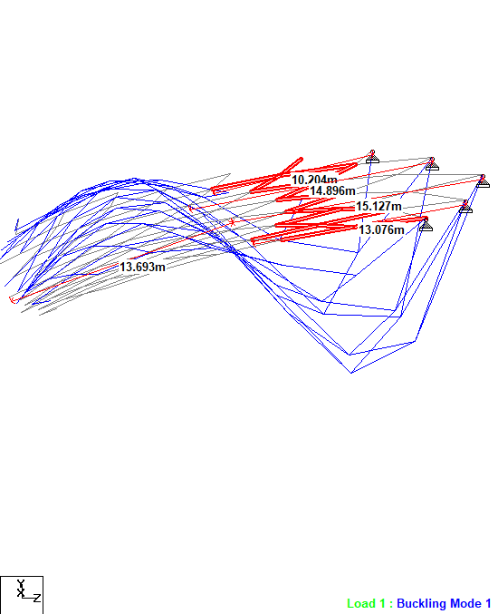
4. By observing the buckling shape (below image- Part of geodesic) it can be seen that approximately 9 members are there in buckling of selected part of geodesic. Each pipe size is 139x6 mm hollow circular section with A_g = 2525 mm^2 and I_z = 5640000 mm^4
5. Taking this portion as a group of members and taking the average length of buckling approximately 14 m.

1st_mode_average_iissij.png


6. Applying Euler's formula to get P_e1 (As per AISC)
= Pi^2 .EI/(kL)^2 = 3.1415^2 x 200000 x 9 x 5640000/(14000)^2 = 511200 N
7. Now for getting modified slender parameter which method/formula I should use. There are factor Cm and B1 and B2 as K factor, first order and second order analysis factor respectively as per Appendix 7 and 8.
I am attaching the appendix of second order analysis also please check and guide me. There is Pr in the equation of Cm but it not squash load, its showing it as axial load.


I have told you the 2 thinks you need to do....
very easy....
Buckling length for member check = length of member
 
but how to get this buckling length. If same 14 m buckling length I will take means my members are failing in slenderness.
 
buckling length for local member check is the true length of the member....from node to node...
for global buckling use an imperfect global structure ...no need of buckling length

buckling length only needed if you use 'hand' formulas from codes
using a real nonlinear computer model no need to specify buckling length

That's the benefit of computer models :)
 
Basically you are saying that, for my STAAD model no need to define effective length. Just I need to apply loads, if my Buckling ratio is greater than 1 means my structure is safe in global buckling. Correct??
 
Dear Klaus,

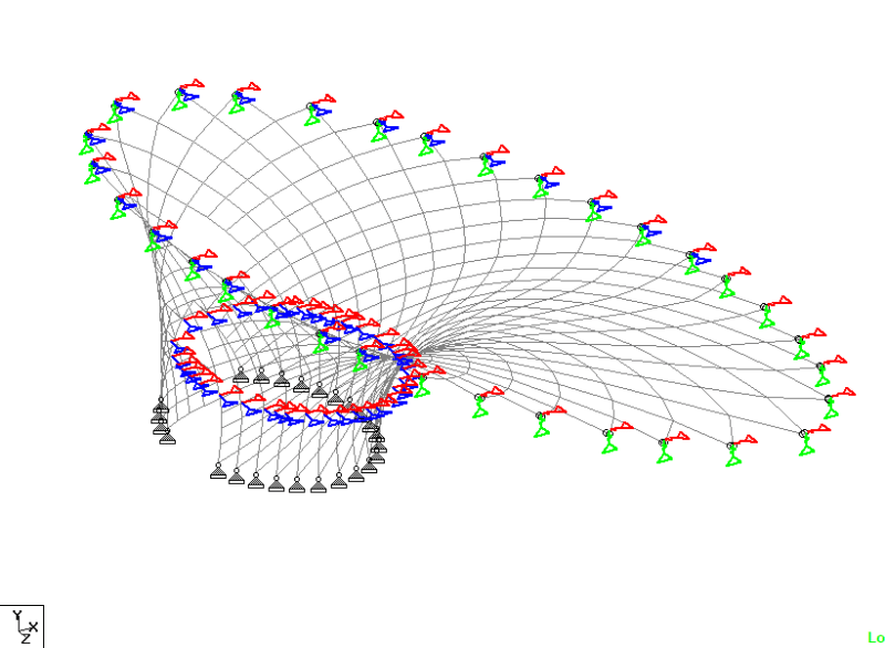
as per your suggestion and my understanding I separated the geodesic structure from the rest of the building for Buckling analysis. I followed below procedure for Global Buckling analysis.

1.separated the Geodesic model (Grid shell).

2. Modelled bottom support as hinge (supported on slab) and top support of space frame with Spring Stiffness (Derived from full Model).

3. Applied loads on geodesic (Acting on it and transferring through space frame both).

4. Added Load combination as repeat load case.

5. Then Run the buckling analysis in STAAD for whole structure of Geodesic.

6. The maximum Buckling factor I got is 4.67 . Which means that- what are the current loads need to increase 4.67 times to buckle the geodesic structure.

Geodesic_only_l7wnrp.png


7. So in this case as it has been proved in STAAD that the current loads are well within the buckling capacity of geodesic, do Its really need to define effective length in Design parameter?? I think here no need to apply the length factor to check the slenderness as those members are not going to buckle individually.

Please guide. If you have some reference please share.
 

No ..not correct
I gave you the 2 necessary steps above....but I repeat once more

1) local check
make buckling check for each member by 'hand' ( spread sheet) ...
use compression force from computer model and member length as buckling length (distance from node to node)
==> this will check each member for buckling

2) global check
take model and make imperfections (depending on the computer program you use ...each one is different)
then make calculation using nonlinear theory
theory second order might be enough but most good program can handen nonlinear theory (Th. III Order)
Now 2 think need to be fulfilled
first you need stable condition....that is you get an result and not an error due to instability
second for the nonlinear results make stress check... (easy to do with the program)

If this is fulfilled ...system is OK

The global buckling factor need to be greater than one of course ti be in stable conditions
but the factor itself is NO design ...it just tells you where about you structure is...but it is not sufficient for design check


Dear Klaus,

can u please give reference or example.
this is first time I am doing this one.
 
Arbu, unless I'm mistaken the buckling analysis in STAAD which you are using is an 'elastic critical buckling analysis'. It is not a 'second order inelastic buckling analysis', which is what Klaus is referring to. I also don't agree in whole with what Klaus is noting, for stability all you need to do is the global analysis he is noting. This gives you the load at which a real member or group of members will fail. There is no need as far as I can tell to then do a further local buckling check? The buckling analysis simply captures the critical buckling behaviour of the 'system', this might be buckling over multiple members acting as a group like your analysis, so checking further local checks adds nothing to the answer you are after (happy to hear any views opposing to this as I'm not an expert in these things, but I know enough to be dangerous!)

A 'second order inelastic buckling analysis' needs to account directly for initial imperfections (i.e. the L/1000 imperfections in real members, and out of plumbness), effect of residual stresses (leads to partial plasticity as loads increase and resulting reduction in stiffness as you reach a plastic stress state, which combined with the imperfections rapidly increases 2nd order effects and hence increase plasticity until you form a plastic hinge that indicates the onset of inelastic buckling), & large and small P-delta effects. Like I noted STAAD does not do this I believe, you need software that does this type of analysis.

An 'elastic critical buckling analysis' does not account for these 2nd order effects. As I explained previously, you can modify the 'elastic critical buckling stress' to a real structural behaviour by applying the code buckling curves. I'll have a read through AISC and try outline how to do this, but it is covered in the Mastan2 modules that I have referenced previously. So if you are after references on how to do this I've mentioned Mastan2 several times, have you undertaken the stability fun modules as these will teach you the fundamentals on simple structures and perhaps address some of the fundamental questions you have?

I mentioned earlier also reading up on the Direct Analysis Method, this would seem like another path to take for your analysis (I've never used it in practice, but I understand it is geared towards the type of thing you are doing, where you are presented with 'what K do I use for my system?'). This method is intended to be a method for assessing stability when selection of a K factor is effectively impossible. Basically you reduce member stiffness (allows for residual stress effects), and apply notional loads to allow for the initial imperfection effects (L/1000 & out of plumbness). Then analyse the structure using a non-linear analysis. You then can design the members using the normal provisions using K=1.0 for all members using the approximated 2nd order design actions from your analysis. The analyses use of the notional loads and reduced stiffness's is intended as a means to directly account for the 2nd order effects and critical buckling mode, and effectively amplifies any design moments. If your design capacity ratio is sufficient, then the structure is deemed stable under that loadcase, if any members fail, then the structure is deemed unstable (increase members until stability is achieved). In a complex structure you might have numerous cases with notional loads to investigate the critical behaviour.

For references on the direct stiffness method I found the AISC Education account on YouTube has multiple video going through in detail how to apply these provisions and the basis for it.

To aid in your understanding of the concepts forget about your complex model for a while and create some simple models for which you know the answer and follow the code procedures using either an elastic critical buckling loads approach, or a direct analysis method (DAM) approach to show the same capacity.

 
I do not know how STADD works ( I Use Dubal programms )

The 2 step procedure I gave above is true in general for stability check

@Arbu
if this is the first time you do that...maybe you should get help form an engineer around you
Stability analysis is not as easy as stress design and just to push buttons and believe what a program says can be very dangerous
 
Arbu, looking through AISC360-16, some comments on applying the provisions in relation to using a critical buckling analysis in lieu of tabulated effective length factors, the K factor in the code:-

The provisions for working out the capacity of a member in compression require you to work out the critical buckling stress, being F_e in equation E3-4. This 'critical buckling stress' is effectively the average stress on a cross section when buckling occurs, it is simply P_cr/A_g, where P_cr is the critical buckling load. This stress is then used in applying the code provisions for determining the buckling load of a 'real' member.

i.e. by applying the code column curve to the column/member/system (this is what eqns E3-2 & E3-3 are doing). You will note in the text for F_e that it notes that F_e can be determined by 'or through a buckling analysis'.

Therefore it stands to reason that when you have the buckling load from a rational buckling analysis that you can use the analysis P_cr/A_g in place of E3-4 equation. Rest of design process is as per normal.

So in summary, how to undertake an analysis using AISC provisions
1. undertake buckling analysis
2. work out Pcr, by taking the buckling analysis load factor and multiplying it by the load in the buckling member.
3. work out F_e = P_cr/A_g
4. proceed as per normal applying eqns E3-2 or E3-3 as required, and finally work out the member buckling force using E3-1

The use of F_e from the analysis embodies the effective length from equation E3-4 (i.e. L_c = KL). There is therefore no need to back calculate or guess lengths like you appear to have been doing. It is simply happening in the background once you have the buckling load from the analysis.

Hopefully this clarifies the process of design by the use of a rational buckling analysis in conjunction with AISC.
 
Dear Agent666,

Thank you for explaining everything. Seems like it will work, I will try to solve and let you know. Thank you once again.
 
Dear Agent666,

I tried to follow the procedure u explained above. The steps I followed are mentioned below.

1.Run the buckling analysis of model for load cases and combinations in STAAD model.
2. Out of all load cases and combination the case having least buckling factor has been selected. (Buckling factor = 4.65 for Load 101- 1.4DL in model)
3. Extracted axial forces (for critical load case-101-1.4DL) of members and considered members having Compression only.
4. Multiplied axial compression force of each member by Buckling factor (4.65) to get buckling load in each member P_cr.
5. then calculated F_e = P_cr/A_g
6. Then check F-y/F_e ratio , I found all values greater than 2.25 , that's why my F_cr (as per Eq E3-3) = 0.877 F_e
7. So my buckling capacity will be P = F_cr x A_g


Is this procedure is correct?
So finally I will check the buckling capacity of each member and take the combine check of buckling with moment. right?

I am attaching the Excel of my calculations and STAAD file also please check.
but I have one doubt in this procedure,
"Some members those are having less axial force in model are having less buckling capacity, but that is not true, Or shall I consider only member having maximum axial force or maximum deflection for buckling analysis." Please guide.
 
 https://files.engineering.com/getfile.aspx?folder=3411d3e8-3971-473a-993b-1da5c8acfee7&file=Geodesic_only.std
hi
I am not sure what you are doing with the excel sheet....but for me this is not entire design for buckling
 
Your step 3 is slightly flawed. Your critical buckling load ratio is only valid for the members that are buckling (refer to the buckling mode shapes). Note I have not reviewed the excel file.

You cannot infer the capacity of the other members from the buckling load of another.

To capture every members critical buckling load you need to investigate sufficient numbers of buckling modes, looking for first mode buckled shapes vs higher modes of buckling. This is I guess the manual part and requires judgement to be used. But the analysis infers that the critical member is really the only one you need to look at, all others have a higher ratio. So if the most critical mode works, the others should work (pays to review a further number of the higher modes to ensure this is the case).

Though with structural symmetry and same member size in a structure you would be picking up the most critical member already (all other members in that scenario have a higher elastic critical buckling load). To pickup buckling of some members in a larger analysis you might need 100's of modes for example and would step past numerous extraneous higher modes for other members before arriving at the one you are interested in.

If in doubt create a simple test model with columns with pinned/fixed ends where effective length factors are known from the code and go through the process to make sure you have implemented it correctly.

Yes after finding the axial capacity you can check other moment/axial interaction checks as you normally would.
 
Hey guys, this is getting scary. This is not a simple structure. Shouldn't we suggest Arbu seek some expert advice and have his design thoroughly checked?
 
Reviving this topic because this structure throws up a question I don't know the answer to.

klaus. said:
You need to do 2 things for stability check

1) global stability
Use your model
impose imperfect structure ( different ways to do that )
do geometric nonlinear calculation (e.g. second order theory)
check if the system is stabel and check stress for the results

2 ) local buckling of the members
do for each member local buckling check 'by hand'
by hand means maybe excel or similar if you software cannot hande this automatically

buckling lenght = lengh of member....from node to node...


Agent666 said:
I also don't agree in whole with what Klaus is noting, for stability all you need to do is the global analysis he is noting. This gives you the load at which a real member or group of members will fail. There is no need as far as I can tell to then do a further local buckling check? The buckling analysis simply captures the critical buckling behaviour of the 'system', this might be buckling over multiple members acting as a group like your analysis, so checking further local checks adds nothing to the answer you are after


Talking in context of the AISC's direct analysis method (DAM), my understanding is that you need to do the local member check using effective length factor K=1.0 because the DAM doesn't adopt modelling of out-of-straightness between nodes. This is accounted for in the strength check rather than in the analysis. DAM saves you having to calculate the value of K. However, for this structure, I think using node-to-node distance is unconservative. These are circular section with no strong or weak axis so the check needs to be done for the direction with the longest unrestrained length. Node-to-node would be the shortest in this case whereas the 'radial' direction has no obvious definition of unrestrained length because all intersecting members at nodes are in the circumferential direction - a judgment still has to be made but it's length instead of K in this case, perhaps by looking at the elastic buckled shape. Thought on whether the above is correct and (if so) what length to use would be appreciated.

Alternatively, we could model the out-of-straightness as well as imperfect node locations - a slight extension of DAM - then just do section checks as Agent666 alluded to. My gut feel is that you'd want the node positions and out-of-straight coordinated to form corrugations in the shape of the geodesic funnel so compression forces will crinkle the 'shell'. Again, thoughts appreciated.
 
Status
Not open for further replies.

Part and Inventory Search

Sponsor