Continue to Site

Eng-Tips is the largest engineering community on the Internet

Intelligent Work Forums for Engineering Professionals

  • Congratulations KootK on being selected by the Eng-Tips community for having the most helpful posts in the forums last week. Way to Go!

Regarding Seismic Analysis of Space frame and architectural feature 1

Status
Not open for further replies.

Arbu

Structural
Mar 25, 2018
69
Dear All,

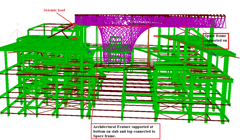
I am designing a space frame which is supported on steel columns. there is a central architectural feature as well. when I am modelling all structure in one model and running seismic analysis, then central architectural feature is taking to much load and members are failing (due to moment and compression) . The central architectural feature is made up of 114x6 mm pipes welded. Please suggest some method of modelling in STAAD such that only columns will carry lateral loads.


seismic_ikrlox.png
 
Replies continue below

Recommended for you

steveh49, keep in mind I don't consider myself that much of an expert in the DAM, know enough to be dangerous!

DAM accounts for second order effects (residual stresses, initial imperfections, etc) through the modification of the flexural and axial stiffness in your analysis model. Therefore you are correct that you do not need to directly model any initial imperfections (typically codes might take this as length/1000). Reducing the stiffness is a way of allowing for these effects in a simple manner.

Correct also that the strength check directly takes account of the stability, due to the use of the notional loads displacing the structure into the buckling shape. Therefore it is quite important for structures with multiple buckling modes to assess multiple sets of notional loads, sometimes these will be acting in opposite directions to initially displace the structure to replicate the critical buckling mode.

This video illustrates an example of this concept whereby multiple buckling modes of the columns are investigated with respect to how the mega-braces and secondary stability bracing interact to ensure global stability of the entire system.

For the structure being discussed here, I believe if you were to use the DAM you would need notional loads at each node. With the direction these loads act corresponding to matching the critical buckling mode. Driving in a way the displacement of the structure to a state at which would replicate the critical buckling mode if the loads carried on incrementally increasing.

The reduction to stiffness directly account for the stability checks, therefore I believe you only need to check the section itself at discrete locations (a section check, vs a member check?), you don't need to check if the structure buckles over some given length, its taken care of by the analysis as all the notional loads and stiffness reductions are allowing for the onset of inelastic buckling. What I believe its replicating and a way of thinking about it is all these second order effects are allowed for and the structure at the end of your analysis is effectively at the point where it is notionally buckling, then you are just showing any point in the structure still has strength such that there is not any inelastic instability (i.e. confirming that nothing is yielding (effectively that some reserve strength exists) that prevents things keeping on moving/rotating/displacing and the structure ultimately becoming unstable and actually buckling).

Regarding your last paragraph, in DAM you can use intermediate node loads to model the imperfections, no need to do it directly. I think you are maybe missing this critical point based on what you have written?

In my mind for a complicated structure with multiple notional node loads acting in all sorts of directions, the use of a rational critical buckling analysis seems a whole lot easier to implement and manage. But maybe that is because I'm far more familiar with its use than the DAM. Both methods should be more widely adopted because assuming effective lengths is a fools game if you have a complicated structure or varying axial loads along a member. You never know you have made a conservative or unconservative guess unless you confirm it with some sort of rational buckling analysis, and then you might as well have done the buckling analysis in the first place with no guessing involved. Most software does this type of analysis these days, but you just have to know what its outputting and how to feed this back into your code equations (some of which was discussed above), and its important to note the value out of the analysis is not the capacity, imperfections/application of the code buckling curves accounting for initial imperfections still need to be undertaken.
 
I like to think of DAM as being the inverse of 'normal' design, in simplistic terms :-

Normally you analyse some structure and then through your code apply notional buckling curves (accounting for 2nd order effects) and assess code strengths against analysis demands.

In DAM you assess the notional buckling behaviour directly in your model and assess analysis demands (including allowances for second order effects) against code strengths directly without further modification.
 
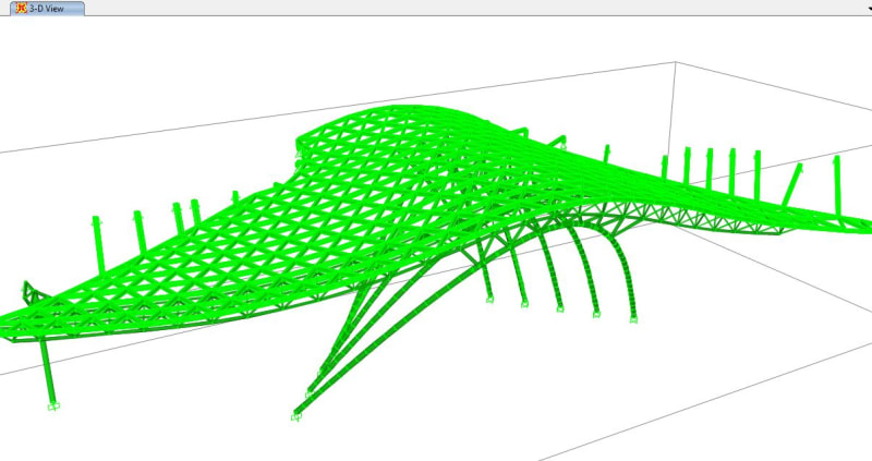
Reminds me of the new entrance at Kings Cross Station, London.

KC_rhfxyi.jpg
 
Thanks for the replies, Agent.

Agent666 said:
DAM accounts for second order effects (residual stresses, initial imperfections, etc) through the modification of the flexural and axial stiffness in your analysis model. Therefore you are correct that you do not need to directly model any initial imperfections (typically codes might take this as length/1000). Reducing the stiffness is a way of allowing for these effects in a simple manner.

My understanding is that the reduced stiffness is not to model initial geometric imperfections, but to approximate the secant stiffness at ULS so the second-order effects are correctly calculated. However, in a DAM analysis, initial out-of-straight is not modelled so the classic pin-pin Euler column (for example) would still have zero bending moment despite reduced stiffness and second-order analysis. This is why the k=1.0 member check needs to be done rather than just a section check. For a sway frame, the DAM analysis would underestimate bending moments (by the amount due to initial out-of-straight) rather than have zero moment.

I haven't watched the video yet as I need to install a video player that will handle the video format.


Agent666 said:
Regarding your last paragraph, in DAM you can use intermediate node loads to model the imperfections, no need to do it directly. I think you are maybe missing this critical point based on what you have written?

Not missing it (it's mentioned in the User Note under section C2.2b) but I would say this strictly puts the analysis somewhere between DAM and the AISC's Advanced Analysis (Appendix 1). See the User Note under section C2.2. But I did think changing the geometry would be more practical for this structure than notional loads. BTW, advanced analysis requires modelling the imperfect geometry and specifically outlaws notional loads so I would tend in that direction.


Agent666 said:
For the structure being discussed here, I believe if you were to use the DAM you would need notional loads at each node. With the direction these loads act corresponding to matching the critical buckling mode. Driving in a way the displacement of the structure to a state at which would replicate the critical buckling mode if the loads carried on incrementally increasing.

That's good information and pretty much answers my question - how sure are you that this produces the critical design case? The AISC guidance on which direction to use for notional loads still assumes a somewhat rectangular structure but the notional loading is fairly intuitive for that case IMO.


Agent666 said:
In my mind for a complicated structure with multiple notional node loads acting in all sorts of directions, the use of a rational critical buckling analysis seems a whole lot easier to implement and manage.

I got the impression from the discussion above that this was a bit impractical unless the conservative case of taking the first buckling mode as setting the buckling load for all members was adopted? (such as Microstran and Space Gass do if you're familiar with them.) Otherwise you still needed to make a judgment call on the effective length of members that weren't involved in the first buckling mode?
 
I'm not intimately familiar with AISC, but I should read it obviously to get the detail right as I'm muddling things up!

Reduced stiffness also models the loss of stiffness at the onset of yielding as it progresses through the section due to the effects of residual stresses.


Yes familiar with both Microstran and spacegass buckling analyses. Further buckling modes are irrelevant in a way for each load case you are looking at. The first critical mode occurs first (lowest buckling load factor). If you think of slowly increase the loads in proportion to this 1st buckling mode, failure/buckling occurs first at an applied load equal to the design actions from the base buckling analysis load case x the load factor. Everything else has a higher buckling load factor and is not unstable at the point the first failure occurs.

For DAM for something with multiple buckling modes I'm guessing you probably need to zero in on the critical buckling shape/mode with a buckling analysis to refine your application of notional loads with each load case to capture the critical mode of failure.

What the buckling analysis method won't tell you is the estimate of second order effects (moment) that DAM tells you. Classic example of this is fixed base cantilever column with vertical load at top acting vertically. Normal analysis offers you nothing regarding the moment to be applied at the point of sway type failure with a given load, DAM gives you an estimate of the moment at the point of instability.

I'd argue for predominantly straight/rectangular frames that the initial imperfections need allowance (either through direct modelling or application of the code buckling curves), but for something with curved members like the structure in this thread the second order moments increase due to initial imperfections are probably dwarfed by the secondary moments due to 'curvy nature' of the structure and eccentricity of the axial loads. I guess what's important is to assess relative contributions and see what does and doesn't need to be allowed for based on the geometry.
 
Dear All,

I am doing another single layer frame (latticed) with free form (same as above). In this we have a third party designer for checking our design.
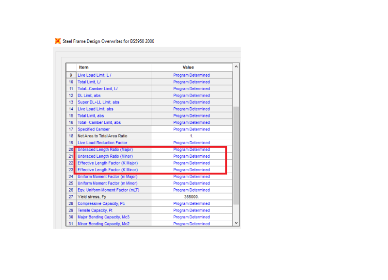
3rd party is modelling our structure in ETABS/SAP000 and they are defining effective length and k factor as programme determined, as in attached image. And running analysis, NO special buckling analysis or second order analysis they are doing.

overwite_q7clml.png


Capture_jzxoup.jpg


is this is enough? is SAP2000/ETABS is capable to determine exactly the buckling shape and calculates factors accordingly??
 
Status
Not open for further replies.

Part and Inventory Search

Sponsor